
Specifications


5/9/13 888-2857-001 4-7
WARNING: Disconnect primary power prior to servicing.
Section 4 Theory of Operation
Platinum VAX-C Series
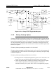
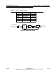
4.4.2 The Modulation Process
The transport stream inputs are applied to the FPGA modulator.
The modulator will process the transport stream and recover the data and the clock. In
some modulation standards, the clocks required to synchronize several circuits in the
signal processing board are phase locked to the recovered transport stream clock.
During the modulation process the FPGA modulator adds forward error correction to
the digitized signal. This forward error correction includes, but is not limited to, data
randomization, Reed-Solomon coding, data interleaving, and trellis coding. Some
modulation methods may use convolutional coding and frequency division multiplex.
The signal is also band-limited using a digital filter.
The FPGA modulator sends the digitized, processed, and bandpass filtered IF signal to
the digital upconverter and precorrector circuit.
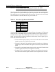
The precorrector uses RTAC to apply precorrection to the digitized IF signal based on
the down converted, digitized RF samples from before and after the high power filter.
The fully processed and precorrected digitized IF signal, resulting from various digital
operating modes, is processed into a 140 MHz (center frequency) IF signal by the DAC
(Digital to Analog Converter).
The 140 MHz IF signal is sent to the upconverter circuit of the up/downconverter board,
where it is heterodyned up to the on channel frequency and amplified. The modulator
maximum output level is 6 dBm (4 mW average) in any digital mode. The 50 watt PA
requires 2.5 mW of input drive power and the 25 watt PA requires 2.24 mW of drive.
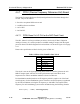
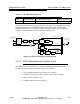
4.4.3 RF Sample Processing
The RTAC algorithm compare the processed and filtered digitized IF signal from the
modulator to the digitized RF samples in order to apply the correct precorrection to the
signal to accommodate the linear and nonlinear distortion. The RF samples for the
RTAC algorithm must be selected one at a time, the level set, the sample down
converted to the 140 MHz IF frequency, and then digitized and sent to the digital
precorrector circuit.
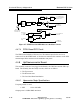
The input to the downconverter is an electronic switch, which is controlled by the signal
processor board.
The level of the selected signal is set to the optimum level for the downconverter mixer
by an attenuator, which is controlled by the signal processing board.