
Specifications


4-4 888-2857-004 5/9/13
WARNING: Disconnect primary power prior to servicing.
Section 4 Theory of Operation
Platinum VAX-C Series
4.4 Modulator Overview
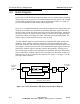
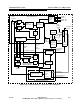
Figure 4-2, on page 4-5 is an overall block diagram of the LPU modulator section.
Refer to it while studying the modulator assembly.
The VAX-C modulator section consists of 7 circuit boards including:
• Signal Processor Board.
• PFRU (Precise Frequency Reference Unit Board.
• Up Down Converter Board. This assembly consists of a UDC Base I/O (input/output)
board and a piggy backed UDC board.
• Power Supply and Low Voltage Distribution Board.
• Battery Backup Option Board.
• Front Panel LED and Switch Board.
• Transmitter I/O (input/output) Interface Board is piggy backed under the right rear
side of the signal processor board. This board can be inserted and removed through
the rear panel of the VAX-C chassis.
The amplifier section of the VAX-C consists of the following:
• Power Amplifier Board, which is mounted in the PA assembly
• PA Interface Board, which is mounted on the left side of the PA assembly.
• AC/DC Converter Board, which is mounted on the AC/DC converter assembly.
Signal flow through the VAX-C is shown by the wide dark lines in Figure 4-2, on page
4-5.