
Specifications


4-2 888-2857-004 5/9/13
WARNING: Disconnect primary power prior to servicing.
Section 4 Theory of Operation
Platinum VAX-C Series
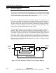
4.3 Block Diagram
See Section 1 in this manual for a basic transmitter overview, model numbers and block
diagram (Figure 1-4, on page 1-9). As a standard practice, the first page of a PC (printed
circuit) board schematic is also a block diagram for that board. Table 1-1 on page 1-5
gives the basic Platinum model numbers and configurations.
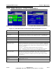
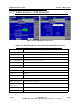
Figure 4-1 is a simplified transmitter system RF block diagram. This diagram shows the
transport stream input to the modulator, the modulator RF output signal connected to
the driver input, and the PA output connected to the PA directional coupler. Outside the
transmitter encloser, the output of the PA coupler is connected to the high power filter
input and the output of the high power filter connected to the directional coupler. The
coupler output is connected to the antenna or the test load.
Two RF feedback signals are connected from the transmitter RF output system to the
modulator. These feedback signals are taken before and after the high power filter,
which follows the PA, and are needed to perform the non-linear and linear RTAC (real
time adaptive correction) precorrection of the modulator RF output signal. The PA (pre
filter) RTAC feedback signal is internally routed in the transmitter. The high power
filter and its output coupler are located outside the transmitter enclosure, and therefore
the post-filter RTAC feedback signal is routed externally from the output coupler to an
SMA connector on the rear panel of the transmitter. See Figure 1-3 on page 1-4 for the
post-filter sample connector.
Figure 4-1 VAX-C Transmitter - RF Interconnection Block Diagram
PA
Output
Coupler
High
Power
PA
Filter
Coupler
Modulator
RF output
to Antenna
PA (Non-Linear) RTAC
RF Feedback Sample
Post-Filter (Linear) RTAC
RF Feedback Sample
Transport
Stream
or Analog
Drivers
Input
VAX-C Transmitter
PA Assembly