
Specifications


5/9/13 888-2857-001 4-1
WARNING: Disconnect primary power prior to servicing.
Platinum VAX-C Series
Section 4
Theory of
Operation
4
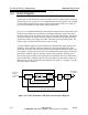
4.1 Introduction
This section contains detailed descriptions of the VAX-C Series transmitter, its internal
sub-assemblies and any pertinent information regarding external assemblies.
This chapter contains four sections:
• Introduction
• Logic Symbols
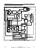
• Block Diagrams
• Modulator Overview
4.2 Active Logic Symbols
Each logic signal has an active and inactive state and a unique name within the system.
To differentiate between active high or active low logic states on the schematics, a
forward slash (/) is placed in front of an active LOW signal name such as /RF_MUTE.
This means that if this logic line is pulled low, the transmitter RF will be muted. By the
same logic, the signal RF_MUTE_LED (an active high signal with no forward slash)
will turn on the RF mute LED when it goes high.
In some cases, a logic signal may act as a toggle with both states active, as with the
signal /ON_OFF, where LOW = ON and a HIGH = OFF. If this signal is inverted it
would be ON_/OFF.