
Specifications


5/9/13 888-2857-001 3-93
WARNING: Disconnect primary power prior to servicing.
Section 3 Operation
Platinum VAX-C Series
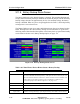
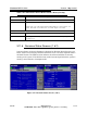
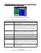
Figure 3-60 ATSC Modulator Status Screen (Page) 2
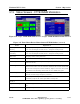
Figure 3-61 Xmtr Home>Exciter Home>Status>ATSC Modulator>Next (screen 2)
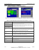
Field Explanation
Modulator Mute Green = OK, Red = Mute. If the digital modulator section is actively
muted, this will indicate red.
Negative Delay In SFN situations, the exciter can only insert (add) delay. If the timing
parameters are improperly set at the transmission adapter or a network
change (such as a substituting a satellite path for a microwave path to get
the transport stream to the exciter) the exciter may determine that based
on the resultant timing, the result indicates that it must remove delay to
actually meet the emission timing. This simply isn't possible and will be
indicated.
Delay Exceeds 1 Second Green = Delay < 1 second, red = delay > 1 second. Transmitter delay, for
SFN (single frequency network) data transmission synchronism, is
measured against the 1PPS (pulse per second) pulse. If transmitter delay
exceeds 1 second, SFN data transmission synchronism is impossible.
Mute to Increase Delay Modulator has determined that it can no longer meet the required timing
and it must mute it's output to re-sync and increase the delay inserted
Mute Count This is the number of times the digital modulator has been muted.
Reset Mute Count Soft Key Pressing this soft key resets the mute count to zero.
Max Delay This is a read back of the maximum delay parameter being carried inside the
Distributed Transmission Packet. It should match the value set in the Distributed
Transmission Adapter. This value is indicative of the maximum transport delay the
network designer / operator expects to see. It's maximum value is 100 nS less than
1 second.
Transport Delay This is the time from when a packet is released inside the transmission adapter
until the time it arrives in the modulator. It also includes a nominal amount of
internal FIFO buffer hold time.