
Specifications

5/9/13 888-2857-001 3-41
WARNING: Disconnect primary power prior to servicing.
Section 3 Operation
Platinum VAX-C Series
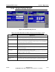
3.5 Setup Screens - ATSC Modulation
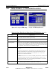
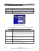
Figure 3-25 on left - ATSC Setup on right - ATSC Modulator Setup Screen 1
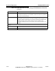
Table 3-20 Xmtr Home>Exciter Home>Setup>ATSC Modulator (screen 1)
Fields Explanation
Power On Input Configures which input will be used after a power failure.
Active Input Selects which input is to be used actively by the modulator.
Input choices and rear panel connectors are shown in "2.7.4 TS
(Transport Stream) Connections" on page 2-14. The input availability and
functionality vary with modulation type. These inputs are not available
for analog modulation.
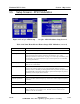
Auxiliary Input This is the backup input to substitute for the Primary if the Switching
Mode is set to Automatic.
Switching Mode Choices are: Auto(matic) or Manual. Selects how the VAX-C is to change
inputs if the selected input is lost. In the Automatic mode, if one input
(Primary-Active or Auxiliary) is missing and the other is present, the input choice
will automatically switch to the input which is present. If both inputs are present,
the Primary (Active) input will be selected.
ATS C M ob i l e DT V Choices are Enable or Disable.
Network Operation Choices are MFN (Multi Frequency Network) or SFN (Single Frequency
Network).
Pilot Test Tone Choices are On or Off.
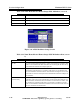
Softkeys
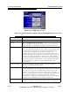
ISP Pressing this soft key displays the ISP ’In-System Programming’ Screen
shown in Figure 3-15 on page 3-22. The ISP screen is used to load
software into the transmitter.