TECHNICAL MANUAL 888-2857-001 Platinum VAX-C Compact Class Transmitter Platinum VAX-C Compact Class Transmitter Technical Manual Harris Broadcast This document covers the following modulations: ATSC/MH DVB-T/H DVBT-2 ISDB-T/H CTTB CMMB DAB DMB T.M. No.
ii 888-2857-001 WARNING: Disconnect primary power prior to servicing.
Technical Assistance Technical and troubleshooting assistance for Harris transmission products is available from Harris field service (factory location: Quincy, Illinois, USA) during normal business hours (8:00 AM - 5:00 PM Central Time). Telephone +1-217-222-8200 to contact the field service department; FAX +1-217-221-7086; or E-mail questions to tsupport@harris.com. Emergency service is available 24 hours a day, seven days a week, by telephone only.
Service Centres Europe Harris Broadcast Eskdale Road, Winnersh, Wokingham, Berkshire, U.K. RG41 5TS Telephone: +44 (0) 118 964 8100. FAX: +44 (0) 118 964 8054 e-mail: TransmittersSupport.Europe@harris.com Asia Leitch Asia Limited & Harris Communications Limited Rm 1015-18, 10/F, Tower 1, Grand Century Place, 193 Prince Edward Road West, Kowloon, Hong Kong Telephone: +852-2174 2504 FAX: +852-2776 0227 email: service.asia@harris.com Americas / Factory Harris Broadcast P.O.
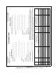
Manual Revision History Platinum VAX-C Compact Class Technical Manual REV. DATE ECN A OCT 2012 P53357 Initial release. B 07May2013 62739 Updates to Sections 1 2 5 5/9/13 Pages Affected / Description 888-2857-001 MRH-1 WARNING: Disconnect primary power prior to servicing.
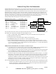
Guide to Using Parts List Information The Replaceable Parts List Index portrays a tree structure with the major items being left most in the index. The example below shows the Transmitter as the highest item in the tree structure. If you were to look at the bill of materials table for the Transmitter you would find the Control Cabinet, the PA Cabinet, and the Output Cabinet.
5/9/13 888-2857-001 WARNING: Disconnect primary power prior to servicing. vii Item ______________________________ Quantity Part Number ________________________________ ______________________________ Ref Des e.g. C21, R100, etc. Item Used On Assembly if Known e.g. C21 used on 992-8025-001 & Schematic 839-8038-991 Comments Guide for Ordering Parts: Please provide as much information as possible to facilitate part substitution as required.
viii 888-2857-001 WARNING: Disconnect primary power prior to servicing.
! WARNING: THE CURRENTS AND VOLTAGES IN THIS EQUIPMENT ARE DANGEROUS. PERSONNEL MUST AT ALL TIMES OBSERVE SAFETY WARNINGS, INSTRUCTIONS AND REGULATIONS. This manual is intended as a general guide for trained and qualified personnel who are aware of the dangers inherent in handling potentially hazardous electrical/electronic circuits. It is not intended to contain a complete statement of all safety precautions which should be observed by personnel in using this or other electronic equipment.
x 888-2857-001 WARNING: Disconnect primary power prior to servicing.
FIRST-AID Personnel engaged in the installation, operation, maintenance or servicing of this equipment are urged to become familiar with first-aid theory and practices. The following information is not intended to be complete first-aid procedures, it is a brief and is only to be used as a reference. It is the duty of all personnel using the equipment to be prepared to give adequate Emergency First Aid and there by prevent avoidable loss of life. Treatment of Electrical Burns 1.
Glossary of Terms Analog Input Board (AIB): An optional circuit card for the modulator section of the low power unit (LPU). It provides the necessary interface to allow the modulator to accept analog video and audio inputs according to the PAL, NTSC, or SECAM standards. ASI (Asynchronous Serial Interface): A streaming format used to carry the MPEG transport stream from the network origination point to the transmitter for modulation onto the RF carrier(s).
COFDM (Coded Orthogonal Frequency Division Multiplex): A transmission technique in which the information content of a complete ensemble (multiplex) is divided and modulated onto a multitude of closely neighboring RF carriers within a channel bandwidth (frequency block). The division of the information payload among a large number of RF carriers ensures that each individual RF carrier has a very low data rate (symbol rate).
permit sending of multimedia information (radio, TV, and data casting) to mobile devices such as mobile phones. Originally developed in South Korea. DUC (Digital Upconverter): A circuit in the LPU modulator section that converts the digital modulated baseband signal to the 140 MHz digital intermediate frequency.
An optional circuit card for the modulator section of the low power unit (LPU). It provides the necessary interface to allow the modulator to accept ETI transport streams according to the DAB digital transmission standard. Ethernet: The physical interface by which the VAX transmitter may be connected to a LAN and/or the Internet to provide web-based supervision. It generally employs an RJ45 connector.
Hierarchical modes: A transmission technique whereby the transmitted data payload is divided into a lower data rate high priority (HP) stream and a higher data rate low priority (LP) stream. Those receivers with difficult reception conditions decode only the more robust HP data stream, while receivers with good reception conditions receive both data streams.
precisely at the ideal locations. However various imperfections in the signal path cause the actual constellation points to deviate from the ideal locations by finite error vectors. The modulation error ratio quantifies the ratio of the desired signal to the undesired error vectors. MER is typically associated with COFDM modulation formats such as DVB or DAB. MCM (Master Control Module): A circuit card in the transmitter control unit (TCU) in dual drive systems.
PS (Power supply): A device that supplies DC electrical energy to one or more electric loads, typically via the rectification of an AC mains electrical input. RF (Radio frequency): An electrical oscillation at the frequency of radio waves in the range of 3 kHz to 300 GHz. In this application, typically a signal in the 168 MHz to 242 MHz frequency range of the VAX transmitter. RS-485: A TIA/EIA standard for serial multipoint communications lines.
Static Delay: A delay function provided by the exciter over a manually settable range of 0 to 1000 ms to compensate for differences in signal processing delays or local propagation conditions for individual transmitters in a single frequency network. Sync (Sync pulse): The horizontal synchronization pulse in the video waveform which, when transmitted, creates the highest level of peak envelope power in the transmitter.
A battery-based system designed to provide power during an AC mains failure event. VGA (Video Graphics Array): A video display standard used by the personal computer industry based on a 640 x 480 pixel resolution. The standard used by the TCU touchscreen in dual drive systems. VHF (Very High Frequency): The radio frequency range of 30 MHz to 300 MHz. In this application, the 168 MHz to 242 MHz frequency band covered by the VAX transmitter.
Table of Contents User Remote Connector . . . . . . . . . . . . . . . . . . .2-11 Transmitter Interface Connector. . . . . . . . . . . . .2-13 TS (Transport Stream) Connections . . . . . . . . . .2-14 External Interlock . . . . . . . . . . . . . . . . . . . . . . . . .2-14 Cooling System. . . . . . . . . . . . . . . . . . . . . . . . . . .2-14 RF Connections. . . . . . . . . . . . . . . . . . . . . . . . . . .2-16 RF Output . . . . . . . . . . . . . . . . . . . . . . . . . . . . . .
Table of Contents PS Module Removal/Replacement . . . . . . . . . . . . 5-8 Power Calibrations . . . . . . . . . . . . . . . . . . . . . . . 5-10 System Factory Fwd/Rfld Calibration . . . . . . . 5-12 DUC/RTAC or UDC Output Status Screen. . . . 3-84 Transmitter I/O Status screen . . . . . . . . . . . . . . 3-85 PFRU Status Screens. . . . . . . . . . . . . . . . . . . . . 3-87 Battery Backup Status Screen . . . . . . . . . . . . . . 3-90 Revisions Status Screens (1 & 2) . . . . . . . . . . .
Table of Contents Offset Delay . . . . . . . . . . . . . . . . . . . . . . . . . . . DAB EDI/IP Input Option. . . . . . . . . . . . . . . . . . Overview . . . . . . . . . . . . . . . . . . . . . . . . . . . . . Installation and Setup . . . . . . . . . . . . . . . . . . . . Inputs/Outputs . . . . . . . . . . . . . . . . . . . . . . . . . Operation . . . . . . . . . . . . . . . . . . . . . . . . . . . . . M2X, LPU or VAX Interface . . . . . . . . . . . . . . GUI Screens . . . . . . . . . . . . . . . . . . . .
Table of Contents 4
Platinum VAX-C Series Section 1 Introduction 1.1 1 Purpose of Manual This manual provides important information for the proper operation and maintenance of the VAX family of air cooled, solid state, VHF transmitters. Schematics and diagrams are provided in an accompanying drawing package. This manual is written for the skilled broadcast maintenance technician and assumes previous experience working with RF broadcast equipment.
Section 1 Introduction 1.2 Platinum VAX-C Series VAX-C Features / Benefits The Harris VAX-C Compact Class transmitter offers the following useful features and benefits: • Easy migration between different modulation standards. Nearly all digital TV and DAB/DMB standards are available by software upgrade. NOTE: If different modulation standards are required, then a new feature key must be entered into the controller to activate additional modulation types and options.
Platinum VAX-C Series 1.3 Section 1 Introduction General Description This section contains a general description of the Platinum VAX-C Series of television transmitters. Included in this section will be descriptions of the control system, amplifier, block diagrams of the various models and system specifications. The VAX-C series of solid state, air cooled, transmitters is designed to synthesize and amplify radio- frequency signals in the VHF broadcast bands III (168 to 242 MHz).
Platinum VAX-C Series Section 1 Introduction Figure 1-3 VAX-C Rear Panel The Platinum VAX-C series of solid state, air-cooled transmitters is designed to synthesize and amplify radio frequency signals in the VHF TV and DAB/DMB broadcast band III 168-242 MHz.
Section 1 Introduction Platinum VAX-C Series 1.4 Transmitter Models VAX-C transmitter model numbers are formed based on the following: ‘V’ stands for VHF Band, while ‘A’ means that air is used for cooling, ‘X’ indicates that the unit is a TV Transmitter, and ’C’ stands for compact class. The number following the VAX prefix stands for the transmitter power level. The suffix indicates the modulation type. The suffix ‘AT’ indicates ‘ATSC’.
Platinum VAX-C Series Section 1 Introduction Table 1-2 Platinum VAX-C COFDM TV Transmitter Models Tx Models Configuration Output Power (average) VAX-50XX-C 2RU 50 W VAX-100XX-C 2RU 100 W NOTES: All power levels given in average power at the transmitter output (prefilter). RU = rack unit. 1RU = 4.45 cm (1.75") NOTE: In the table above the suffix XX is an indicator of modulation type. The following suffixes are used: DV=DVB-T/H, T2=DVB-T2, IS=ISDB-T, CT=CTTB, CM=CMMB.
Platinum VAX-C Series 1.5 Section 1 Introduction VAX Transmitter System VAX-C transmitters feature solid-state design and utilize a FET-based power amplifier (PA) module to amplify the RF signal. In addition to RF drive power from the exciter stage, the PA module utilizes 50V DC power, supplied by a switch mode power supply (PS) module. The PA module type varies with power level. The VAX-C features two cooling fans that can be changed by removing the front panel while the transmitter is on-air.
Section 1 Introduction Platinum VAX-C Series Platinum VAX-C transmitters include a Web enabled remote GUI interface that provides comprehensive remote control and monitoring of data points within the transmitter. It includes an SNMP (simple network management protocol) manager which allows integration with most control systems via the Internet or LAN. 1.6 Operating Voltages Single phase, 100 to 240 V AC, auto-ranging, +/-10%, 50/60 Hz, one IEC C15 inlet.
Section 1 Introduction Platinum VAX-C Series 1.7 Block Diagram Figure 1-4 on page 1-9 contains a system block diagram showing the basic RF signal flow and configuration for a Platinum VAX-C transmitter. PA Module Battery Backup Option Figure 1-4 VAX-C Simplified Block Diagram 5/9/13 888-2857-001 WARNING: Disconnect primary power prior to servicing.
Section 1 Introduction 1.8 Platinum VAX-C Series Transmitter Accessories The VAX-C chassis contains the basic VAX transmitter. Additional options are available and may be present in a VAX-C transmitter system. In as much as these accessories do not significantly change the functioning of the core transmitter itself, it is understood that this manual addresses customized transmitter configurations that may contain one or more of these options.
Platinum VAX-C Series 1.9 Section 1 Introduction VAX-C Exciter/Controller The VAX-C exciter section is a transmitter RF signal source. It receives the program material to be transmitted in the form of a digital transport stream and generates a lowlevel on-channel RF signal. It performs pre-corrections for non-linear distortions which occur in the transmitter RF power amplifier and for linear distortions/group delay which occur in the high power filter.
Section 1 Introduction Platinum VAX-C Series depending on the modulation standard. See section 3 for modulation dependent input connector configurations. The modulation process is fully digital, with analog circuits used after the D/A converter to up-convert the IF signal to the desired channel.
Section 1 Introduction Platinum VAX-C Series 1.10 VAX-C Specifications NOTE: Specifications subject to changed without notice. Unless otherwise noted, these specifications apply at the output of a Harris supplied mask filter. 1.10.
Platinum VAX-C Series Section 1 Introduction Table 1-4 General Specifications Item Specification Environmental 32° to 113° F (0° to 45° C) up to 6,560 ft (2,000 m) AMSL, de-rate 3.6° F (2° C) per 984 ft (300 m) of elevation. 95% relative humidity, noncondensing Physical (H X W x D) 2RU x 19" x 23" (2RU x 483 mm x 584 mm); 2RU= 3.5" (88.9 mm) Weight 25 lbs (11.
Section 1 Introduction Platinum VAX-C Series 1.10.2 COFDM Specifications Table 1-5 COFDM Transmitter Specifications (DVB-T/T2, ISDB-T, CMMB) Item Specification Power Output (before filter) 50 W, 100 W Output Power Reduction 0 dB to -10 dB Power Stability ±0.5 dB Shoulder Level <-37 dB MER >34 dB END ≤0.7dB Frequency Stability ±150 Hz/month without PFC/GPS <0.
Platinum VAX-C Series Section 1 Introduction 1.10.3 ATSC Specifications Table 1-6 ATSC Transmitter Specifications Item Specification Power Output (before filter) 40 W, 180 W Output Power Reduction 0 dB to -10 dB Power Stability ±0.5dB Shoulder Level <-35dB EVM >27dB (<4%) Frequency Stability 1 ±150 Hz/month without PFC/GPS <0.
Section 1 Introduction Platinum VAX-C Series 1.10.4 DAB/DMB Specifications Table 1-7 DAB/DMB Transmitter Specifications Item Specification Power Output (before filter) 75 W, 150 W Output Power Reduction 0 dB to -10 dB Power Stability ±0.25 dB MER DAB/DMB (OFDM) ETSI TR101 496-1 25 dB MER prior to optional mask filter. Frequency Stability <5x10⁻¹⁰ per day (OCXO aging) Standards DAB ETSI EN 302077 Response Variation 0.
Platinum VAX-C Series Section 1 Introduction Table 1-7 DAB/DMB Transmitter Specifications Item Specification 1 pps input BNC-female, 50 ohm (high Z), TTL level Reference Frequency Input SMA-female, 50 ohm, 0.1/0.5/1/2.048/5/10 MHz, -7 to + 15 dBm Monitoring Outputs - ETI OUT - ETI-frame - RF monitor (low power stage) - 1 Hz (1 pps signal) - Reference frequency 10 MHz - Incident and reflected signal Tx output (optional) 1-18 888-2857-001 WARNING: Disconnect primary power prior to servicing.
Platinum VAX-C Series Section 2 Installation / Initial Turn-On 2.1 2 Introduction This section includes the information necessary for installation and initial turn on of a Platinum VAX-C, solid state, air cooled, VHF TV transmitter. Due to the modular nature of the VAX-C, all models have similar installation and testing procedures. 2.
Platinum VAX-C Series Section 2 Installation / Initial Turn-On 2.4 Documentation The following is a list of documentation that ships with the transmitter. Find and save all documentation. A Document Package includes: 1. Technical manual 2. Drawing Package with a set of applicable system level schematics for the transmitter system 3. Application notes and manuals for ancillary equipment may be packed individually with system components. 2.4.
Platinum VAX-C Series 2.5 Section 2 Installation / Initial Turn-On Installation NOTE: This equipment is intended only for installation in a RESTRICTED ACCESS LOCATION. Steps in the installation section are numbered in each section. As each step is completed, the step number can be circled to indicate completion. This provides a quick confidence check at the end of the procedure that no steps were skipped.
Section 2 Installation / Initial Turn-On Platinum VAX-C Series NOTE: Failure to follow these installation instructions may void the warranty. The transmitter should be placed where it will have adequate room to access the front and rear panels. There are several drawings included in the drawing package to help plan the transmitter placement: STEP 1 Open the box and remove the packing material that surrounds the transmitter. STEP 2 Place the transmitter in position. 2.5.
Platinum VAX-C Series 2.6 Section 2 Installation / Initial Turn-On Transmitter AC and Ground Connections NOTE: AC connections will be similar across all Platinum VAX-C models. Be sure to verify all connections using the correct schematic drawings. The VAX-C does not have an AC ON/OFF switch. Power is applied to the unit by plugging an energized power cord into the AC connector (IEC C15) on the back of the unit.
Section 2 Installation / Initial Turn-On Platinum VAX-C Series Figure 2-1 VAX-C Safety Ground Connection (without rack) A safety ground wire is required for each AC mains input and they should be connected to the station ground system. In instances where the VAX-C is installed in customer or harris supplied racks each component should have a safety ground connection to the rack. 2-6 888-2857-001 WARNING: Disconnect primary power prior to servicing.
Platinum VAX-C Series 2.6.4 Section 2 Installation / Initial Turn-On Cabinet Ground Strap Connect a ground strap from the cabinet's copper ground buss bar (shown in Figure 2-2) to the station ground. The copper strap must be at least 5cm wide and 0.5mm thick. To prevent ground loops, do not connect this strap to the ground of another piece of equipment, but instead, connect directly to the main station ground system.
Section 2 Installation / Initial Turn-On Platinum VAX-C Series CASE, AN EXTERNAL CIRCUIT PROTECTION DEVICE TO HANDLE THE ENTIRE TRANSMITTER LOAD AT THE MAIN AC DISTRIBUTION POINT IS STILL REQUIRED, IN ACCORDANCE WITH PREVAILING LOCAL SAFETY NORMS. ! WARNING: USER SHOULD NOT ALTER OR DISCONNECT ANY PROTECTION DEVICES.
Section 2 Installation / Initial Turn-On Platinum VAX-C Series 2.7 Signal and Sample Connections This section contains descriptions of signal and sample connections on the rear of the VAX-C transmitter. Figure 2-3 VAX-C Rear Panel 2.7.1 Table 2-2 Connection GPS (SMA) Rear Panel Connections Rear Panel Connections Description GPS antenna input to the internal GPS receiver. Provides +5 VDC at 0.15 Amps maximum for an amplified GPS antenna.
Platinum VAX-C Series Section 2 Installation / Initial Turn-On Table 2-2 Connection Rear Panel Connections Description 10MHZ REF INPUT BNC, female connector is the (optional) 10 MHz reference frequency input. It is used when precise control of the exciter’s pilot frequency is required. Normal signal input range is -10 to +10 dBm. The input impedance is 50 ohms. USER REMOTE 25 pin, female, D sub connector. See pinout in Table 2-3 below. TRANSMITTER INTERFACE 25 pin male D sub connector.
Platinum VAX-C Series 2.7.2 Section 2 Installation / Initial Turn-On User Remote Connector This 25 pin female connector is labeled ’User Remote’ and located on the rear panel. It can be used for remote control and monitoring on standalone transmitters (non-racked systems).
Section 2 Installation / Initial Turn-On Platinum VAX-C Series NOTE: The alarms noted in the above table report the following functions and are mapped to the Front Panel LEDs as follows: 2-12 • Alarm 0: Output/Mute (If either Output or Mute LED is RED or ORANGE, Alarm is Faulted.) • • Alarm 1: System (If System LED is RED or ORANGE, Alarm is Faulted.) Alarm 2: Power Supply (If Power Supply LED is RED or ORANGE, Alarm is Faulted.
Section 2 Installation / Initial Turn-On Platinum VAX-C Series 2.7.3 Transmitter Interface Connector The 25 pin, male, connector is labeled Transmitter Interface and located on the VAX-C rear panel. It can be used for remote control and monitoring on standalone transmitters.
Section 2 Installation / Initial Turn-On 2.7.4 Platinum VAX-C Series TS (Transport Stream) Connections The TS input connectors are type BNC, female. TS input connector impedances are 75 ohms. Belden 8281 or similar high-quality video cable can be used to deliver this signal to the VAX-C over a distance of up to 1000 feet.
Platinum VAX-C Series Section 2 Installation / Initial Turn-On The front panel can be removed for maintenance while the transmitter is operating but the panel should be in place during normal operation. The 12Vdc fans can be changed while the transmitter is operating. See Section 5.7 on page 5-23 for replacement instructions. NOTE: Prior to start-up, the cooling fans should be visually checked to make sure there are no obstructions.
Section 2 Installation / Initial Turn-On Platinum VAX-C Series 2.10 RF Connections 2.10.1 RF Output Prior to operation the transmitter RF output connector must be connected to a known good test load or antenna with a high quality 50 ohm RF cable. A patch panel may also be used if switching between load and antenna is desired. A type N male connector is needed for the transmitter output side of the cable. The VAX-C output connection is located on the rear panel see Section Figure 2-5 on page 217.
Platinum VAX-C Series Section 2 Installation / Initial Turn-On Figure 2-5 VAX-C RF Connections 5/9/13 888-2857-001 WARNING: Disconnect primary power prior to servicing.
Section 2 Installation / Initial Turn-On Platinum VAX-C Series 2.11 Transmitter Power Up The VAX-C transmitter is now ready to produce RF power. The critical setup steps have been performed. Some additional setup may be required to setup transport stream handling, set RTAC states, system references, etc. If valid transport streams are not present RF output may be inhibited for DVB-T systems.
Section 2 Installation / Initial Turn-On Platinum VAX-C Series STEP 9 Use the LCD screen and control buttons to set RTAC to Adapt mode. Navigate to Setup>Adaptive>Power on LIN and set to Adapt. Navigate to Setup>Adaptive>Power on NON-LIN and set to Adapt. STEP 10 It may take a few minutes for RTAC to adapt and correct the signal. STEP 11 End of procedure. 2.
Section 2 Installation / Initial Turn-On 2-20 Platinum VAX-C Series 888-2857-001 WARNING: Disconnect primary power prior to servicing.
Platinum VAX-C Series Section 3 Operation 3.1 3 Transmitter Control This section gives detailed operational information for the Platinum VAX-C Series Solid-State VHF TV transmitter. Information pertains to the operation and navigation of the front panel controls and the web interface. The VAX-C can be operated from the LCD control panel on the front of the unit or with the web browser interface which is accessed via computer.
Section 3 Operation 3.1.1 Platinum VAX-C Series Transmitter Control Panel The VAX-C transmitter front control panel is shown in Figure 3-1. It contains an LCD screen, control buttons and LED’s. Figure 3-1 VAX-C Front Panel. Table 3-1 Front Panel Control Buttons Field Explanation STATUS Displays the Status Menu. POWER Displays model number, forward/reflected power levels and allows selection of linear and non-Linear correction - Stored, Adapt, Hold or Bypass.
Section 3 Operation Platinum VAX-C Series NOTE: Neither the feature key nor the modulation settings can be changed using the LCD interface. These settings can only be changed with the web browser interface. 3.1.2 LCD Menus LCD menu trees can be found below in Figures 3-2 Power, 3-3 Status, & 3-4 Setup. Web screens are organized in a similar fashion.
Section 3 Operation ON-AIR DATA DIG SIGNAL PATH PFRU (PLL) UP/DOWN CONVERTER AMP PA: PA1: PA VOLTAGE: 50V OUTPUT: FWD PWER: 50.0W RFLD PWR: 0.0W VSWR: 1.0:1 Platinum VAX-C Series UPCONVERTER: IF LEVEL: 757 RF LEVEL: 2484 DOWNCONVERTER: PRE-FILTER LEVEL: 93% POST FILTER LEVEL: 0% LO: LO LEVEL: 1.1 dBm PFRU FPGA PROG: OK PFRU COMM: OK EXT 1PPS: N/A EXT 10 MHz: N/A INT 1PPS: OK 54 MHz CLOCK: OK 10 MHz CLOCK: OK IF PLL LOCK: OK RF PLL LOCK: OK IF LO REF: 54MHz GPS PWR: OK #SAT DETECT: 9 LAT: N39.
Section 3 Operation Platinum VAX-C Series SYSTEM SETTINGS ADAPTIVE XMTR POWER SETTINGS FWD POWER REF: 50W % OF FWD POWER REF: 100% FWD POWER THRESH.
Section 3 Operation 3.1.3 Platinum VAX-C Series Front Panel LEDs Table 3-2 provides information on the front panel LEDs. Additional information on LEDs and the faults that activate them are given in the fault tables in Section 6.3. Table 3-2 Status LEDs Status LEDs States Explanation TS INPUT Green = OK Amber/Yellow = Warning Red = Fault Represents the availability of the Transport Stream input data to the Modulator. The behavior of the TS INPUT LED varies with modulation standard.
Section 3 Operation Platinum VAX-C Series Table 3-2 Status LEDs OUTPUT Status LEDs States Green = OK Amber/Yellow = Warning Red = Fault Explanation Represents the status of the RF output for the system. When the transmitter is switched off, the OUTPUT LED is either off or green, depending on the factory system setup. Green: The transmitter is switched on, and the RF output level is greater than the FWD POWER THRESH (also called FWD LOW PWR WARNING) setting.
Section 3 Operation 3.2 Platinum VAX-C Series Xmtr Home Screen The web browser interface is designed to provide complete control and monitoring of the transmitter. The menu sections are described in this section of the manual. Generally, the information found on the web browser screens can also be found on the LCD menus. NOTE: Neither the feature key nor the modulation settings can be changed using the LCD interface. These settings can only be changed with the web browser interface.
Section 3 Operation Platinum VAX-C Series Figure 3-6 Xmtr Home Screen Table 3-3 Xmtr Home Screen Window Description LPU Sub Window Exciter Displays the Exciter Home screen which is the access point for exciter settings, status and fault log screens. Drv Displays the LPU Driver and PA screen which gives amplifier FET current, temperature and voltage. Output Displays the Output information screen which displays forward power, reflected power and VSWR levels.
Section 3 Operation 3.2.1 Platinum VAX-C Series Output Screen Figure 3-7 Output Screen Table 3-4 Xmtr Home>Output Field Explanation Output Information Sub Window Fwd Power Output of transmitter in W. Rfld Power Reflected power in W. VSWR Voltage standing wave ratio. Softkeys Xmtr Home Displays the Xmtr Home screen. Exciter Home Displays Exciter Home screen. 3-10 888-2857-001 WARNING: Disconnect primary power prior to servicing.
Section 3 Operation Platinum VAX-C Series 3.2.2 Amplifier Screen The Amplifier screen can be accessed from the Xmtr Home page by pressing either the Amp button on right or Amp icon in the LPU sub window. It contains amplifier status and operational information. Figure 3-8 Amplifier Screen Table 3-5 Xmtr Home>LPU PAs Window Description Amplifier Sub Window Current Displays the FET drain current in amps. Fault levels are 2 A for 75/50/90 W amp or 11 A for 150/100/180 W amp.
Section 3 Operation 3.2.3 Platinum VAX-C Series Configuration Screens Figure 3-9 System Configuration Screens 1 & 2 Table 3-6 Field Xmtr Home>Config Explanation Fwd Low Pwr Warning Set the minimum forward power in watts (W) below which a warning is indicated. If the transmitter output power drops below this level, the forward power bar and Output LED will turn yellow. This value must be lower than Nominal power.
Section 3 Operation Platinum VAX-C Series Table 3-6 Xmtr Home>Config Field Explanation % of Fwd Pwr Reference Set the percentage of actual transmitter output power. (Valid range 0 - 100%) If the Fwd Power Reference = 1000W, and the % of Fwd Pwr Reference = 75%, then the actual forward power reference will be 750W. Fwd Power Reference Set the desired forward power of the transmitter in watts (W).
Section 3 Operation 3.2.4 Platinum VAX-C Series System Calibration Screens Refer to ’System Calibration’ screen shown in Figure 3-10. The Calibration screens walks the user through the calibration procedure. Figure 3-10 System Calibration Screen & Menu Table 3-7 Field Xmtr Home>Config>Cal Explanation Factory Fwd/Rfld Factory Fwd/Rfld calibrates the system forward and reflected power meter. Factory calibration is used as a reference calibration across the VHF band.
Section 3 Operation Platinum VAX-C Series Table 3-7 Xmtr Home>Config>Cal Field Cal Complete Explanation Once the user has completed all desired calibrations, the Cal Complete button MUST be pressed to return the system to previous mode of operations.This will allow the system to resume Auto power control mode. If the user does not press the Cal Complete button the system will remain in Manual power control mode until navigating away from the Cal screen.
Section 3 Operation Platinum VAX-C Series hex value by 0x0001 (1 decimal) increments. The double arrows will increase or decrease the RF DAC hex value by 0x0010 increments (32 decimal). Due to the delayed update rate of the web browser, the user should not rely on the RF DAC Value displayed on the GUI to determine if power is being raised real time, as this can cause undesired overshoots. Instead the user is advised to monitor their power meter at all times while adjusting the output power.
Section 3 Operation Platinum VAX-C Series 3.3 Exciter Home Screen Refer to Figure 3-12 on page 3-17 Exciter Home Screen. This screen gives access to the basic command inputs, status outputs, output indications and chart graphics necessary for the day-to-day operation of the VAX-C exciter section. Descriptions of the various home screen sections are given in the following table. The on air performance data comes from the post mask filter sample, and is not switchable.
Section 3 Operation Table 3-9 Platinum VAX-C Series Exciter Home Screen Window Description Main/Standby This field indicates the on-air status. In a dual drive system, an active transmitter will display Main (green field). The inactive exciter will display Standby (in blue). Mute/MUTE This field indicates the mute status of the exciter section. If RF output is muted, this field displays MUTE (uppercase, red field). If the output is not muted, the field displays Mute (lowercase, green field).
Platinum VAX-C Series Section 3 Operation NOTE: The LSB, USB, and in band intermodulation products are caused mainly by the transmitter’s non-linear distortions due to poor power amplifier linearity and phase distortion. They are mainly developed in the PA stage. If the amplifier is substantially linear, the shoulders will be -36 dB or lower. As the non-linear distortions increase, the shoulder levels will rise above -36 dB. Unequal USB and LSB shoulder levels indicate the presence of phase distortion.
Section 3 Operation 3.3.1 Platinum VAX-C Series Fault Log screens Refer to Fault Log -All Faults screen Figure 3-13 on page 3-20. Active warnings are displayed in yellow, active faults are displayed in red. Select Next Page soft keys to view additional Fault Log pages. Figure 3-13 Fault Log - All Faults (left) & Active Faults Screens (right) Table 3-10 Xmtr Home>Exciter Home Screen Window Description Softkeys Reset Log Permanently clears inactive faults and warnings from the display.
Section 3 Operation Platinum VAX-C Series 3.4 SETUP SCREENS, All Modulation Systems From the ’Xmtr Home’ Screen Figure 3-6 on page 3-9 select the ‘Exciter Home’ soft key and then select ’Setup’. Setup subscreens are accessed from this Main Setup Screen. Figure 3-14 Setup Screen Table 3-11 Xmtr Home>Exciter Home>Setup Field Explanation User Settings See 3.4.7, on page -37. Transmitter I/O Only available for select modulations. See Figure 3-18 on page 3-31. PFRU See 3.4.5 on page 3-33.
Section 3 Operation 3.4.1 Platinum VAX-C Series ISP (In-System Programming) Screen See "5.2 PA Module Removal and Replacement" on page 5-2 for information regarding updating software. Figure 3-15 Xmtr Home>Exciter Home>Setup>ISP Table 3-12 Xmtr Home>Exciter Home>Setup>ISP Fields Explanation File to Upload Enter name and location of file containing latest software. Filename ending in .s19 must be entered. Settings files can also be entered here. Browse Press button to locate file to upload.
Platinum VAX-C Series ! Section 3 Operation CAUTION: TRANSMITTER WILL BE OFF-AIR DURING RESET OR PROGRAMMING FORCED REBOOT. 3.4.1.1 Save Settings Soft Key Selecting the Save Settings soft key on the ISP screen saves a copy of the current user settings stored in EEPROM. See additional instructions for saving and restoring VAX-C settings in "5.13.1 Saving and Recalling Settings" on page 5-46. 5/9/13 888-2857-001 WARNING: Disconnect primary power prior to servicing.
Section 3 Operation 3.4.2 Platinum VAX-C Series RTAC Setup Screens 1 & 2 Figure 3-16 RTAC Setup Screens 1 & 2 Table 3-13 Xmtr Home>Exciter Home>Setup>DUC/RTAC Field Explanation Linear: RF feedback sample is taken after high power filter. Success/Attempt x/x The digit to the right of the / indicates the number of times that corrector attempted to make a correction. The digit to the left of the / indicates the number of times the corrector succeeded in making a correction.
Section 3 Operation Platinum VAX-C Series Table 3-13 Xmtr Home>Exciter Home>Setup>DUC/RTAC Field Bypass Explanation Pressing the Bypass soft key turns it orange. Selecting Bypass turns the selected corrector OFF. Correction is not engaged. Nonlinear: RF feedback sample is taken before the high power filter. Success/Attempt x/x The digit to the right of the / indicates the number of times that corrector attempted to make a correction.
Section 3 Operation 3.4.2.1 Platinum VAX-C Series Storing an RTAC Correction Set From the Stored Correction Sets sub window, up to four RTAC correction setups can be saved in Set 1 through Set 4. There is an option to rename each stored setup. The setup can be stored for many reasons, such as when the transmitter was first installed, or after transmitter maintenance. This feature is also useful in comparative testing. Follow the procedure below to save an RTAC Correction setup.
Section 3 Operation Platinum VAX-C Series 3.4.3 DUC/RTAC Setup Screen 3 & 4 Figure 3-17 RTAC Setup Screens 3 & 4 Table 3-14 Xmtr Home>Exciter Home>Setup>DUC/RTAC>Next & >Next Field Explanation Peak Reduction Peak Reduction limits the RF peak power output of the transmitter to provide optimum RTAC performance, while preventing nuisance transmitter PA overdrive trips. In most cases, default settings should be used. Non-Linear Range (dB) Green if Enabled. Set in dB.
Section 3 Operation Platinum VAX-C Series Table 3-14 Xmtr Home>Exciter Home>Setup>DUC/RTAC>Next & >Next Field Explanation RTAC Profiles: Profiles are used to tune the RTAC for various linear and nonlinear operating conditions. Profile choices for linear and non-linear correction are available. The correct profile will improve RTAC performance. Linear Drop menu and select: Basic, Short, Long, Max, Basic Offset, Short Offset, Long Offset, Max Offset.
Platinum VAX-C Series Section 3 Operation up to this limit will be linearized by nonlinear RTAC correction. The peak power out of the exciter must be limited to protect the following amplifier stages. NOTE: If this limit is too low, in-band and out-of-band intermodulation products will increase due to the signal clipping. If the limit is too high, the RTAC nonlinear corrector performance may be degraded due to high peak stretch.
Section 3 Operation Platinum VAX-C Series Nuisance overdrive trips can be avoided by setting the Max Crest Factor parameter section of the RTAC Peak Reduction sub window in RTAC Setup Screen 3, on left Figure 3-17 on page 3-27. Nuisance overdrive trips will typically occur within 30 minutes to 1 hour after transmitter operation with RTAC is first started.
Section 3 Operation Platinum VAX-C Series • MAX OFFSET Profile Nonlinear: For non-linear RTAC correction, the named profiles should be tried before the numbered profiles. Most transmitters should use BASIC or BASIC MEMORY. However, if they do not give satisfactory adjacent channel inter-modulation performance, a higher profile such as HIGH or HIGH MEMORY should be used. Nonlinear profile choices are: • • • • • • • • • 3.4.
Section 3 Operation Platinum VAX-C Series Table 3-15 Xmtr Home>Exciter Home>Setup>Transmitter I/O Field Explanation Transport Stream Sub Window Active Monitor Output Displays active transport stream. ASI(HP1), ASI(LP1), SMPTE 1 ASI (HP 2), SMPTE 2 ASI (LP 2), or Follow Input Stream. Softkeys Setup Displays Setup screen. Exciter Home Displays Exciter Home screen. 3-32 888-2857-001 WARNING: Disconnect primary power prior to servicing.
Section 3 Operation Platinum VAX-C Series 3.4.5 PFRU Setup Figure 3-19 PFRU Setup Screen Table 3-16 Xmtr Home>Exciter Home>Setup>PFRU Field Explanation CHANNEL SETUP sub window Frequency (MHz) Enter licensed frequency in MHz with decimals. SFN Offset (Hz) Field is available if SFN option is installed and functioning. 10MHz OXCO REFERENCE sub window System Reference - Internal GPS (from internal GPS receiver) Ext. 10 MHz reference input Ext.
Section 3 Operation Platinum VAX-C Series Table 3-16 Xmtr Home>Exciter Home>Setup>PFRU Field Explanation Discipline Reference OCXO manual setting, from 1% to 100%, is obtained by entering as a number in the range of 1 to 100. This provides a control voltage for the 10 MHz OCXO reference oscillator when Manual setting of the System Reference is selected.
Platinum VAX-C Series 3.4.6 Section 3 Operation Remote Communications Screens Figure 3-20 Remote Comms Ethernet Screen 1 Figure 3-21 Remote Comms RS232 & CAN and SNMP 5/9/13 888-2857-001 WARNING: Disconnect primary power prior to servicing.
Section 3 Operation Platinum VAX-C Series Table 3-17 Xmtr Home>Exciter Home>Setup>Remote Communications Field Explanation Rear Ethernet Sub Window MAC Address Fixed rear Ethernet port MAC (Media Access Control) address is displayed. Mode Select DHCP (Dynamic Host Control Protocol) or Static. If Static is selected, click into and fill fields (obtained from your IT system administrator): IP, Gateway, & Subnet Mask.
Section 3 Operation Platinum VAX-C Series Table 3-17 Xmtr Home>Exciter Home>Setup>Remote Communications Field Explanation Softkeys Setup Displays Setup screen. Exciter Home Displays Exciter Home screen. 3.4.7 User Settings Screen Figure 3-22 User Settings Screen Table 3-18 Xmtr Home>Exciter Home>Setup>User Settings Fields Active Users Explanation Lists active Engineer level and NetAdmin level users that are logged into LPU via web browser. Softkeys Setup Displays Setup screen.
Section 3 Operation Platinum VAX-C Series See 5.12.3 on page 5-33 for additional information on password change procedures. Figure 3-23 Netadmin Screens 3-38 888-2857-001 WARNING: Disconnect primary power prior to servicing.
Section 3 Operation Platinum VAX-C Series 3.4.8 System Settings Screens Figure 3-24 System Settings Screens Table 3-19 Xmtr Home>Exciter Home>Setup>System Settings & >Next Fields Explanation Page Title Allows user to change the reference title located at the top of the screen above the forward power bar. This title is shown on every screen. Feature Key Enter a factory supplied feature key. Note: The new feature key will become active only after a transmitter reboot.
Section 3 Operation Platinum VAX-C Series Table 3-19 Xmtr Home>Exciter Home>Setup>System Settings & >Next Fields Explanation Softkeys Setup Pressing this soft key displays the Main ’Setup’ Screen in Figure 3-14 on page 3-21. This screen accesses the various setup screens for the transmitter. See Section "3.4 SETUP SCREENS, All Modulation Systems" on page 3-21 Exciter Home Pressing this soft key displays Exciter Home Screen, Figure 3-12 on page 3-17.
Section 3 Operation Platinum VAX-C Series 3.5 Setup Screens - ATSC Modulation Figure 3-25 on left - ATSC Setup on right - ATSC Modulator Setup Screen 1 Table 3-20 Xmtr Home>Exciter Home>Setup>ATSC Modulator (screen 1) Fields Explanation Power On Input Configures which input will be used after a power failure. Active Input Selects which input is to be used actively by the modulator. Input choices and rear panel connectors are shown in "2.7.4 TS (Transport Stream) Connections" on page 2-14.
Section 3 Operation Platinum VAX-C Series Table 3-20 Xmtr Home>Exciter Home>Setup>ATSC Modulator (screen 1) Fields Explanation Status Displays Status screen. Setup Displays Setup screen. Exciter Home Displays Exciter Home screen. Figure 3-26 ATSC Modulator Setup Screen 2 Table 3-21 Xmtr Home>Exciter Home>Setup>ATSC Modulator>Next (screen 2) Fields Explanation Tier ID Tier of the network that this transmitter / exciter corresponds to in accordance with ATSC's A/110 standard.
Section 3 Operation Platinum VAX-C Series Table 3-21 Xmtr Home>Exciter Home>Setup>ATSC Modulator>Next (screen 2) Fields Explanation DFS Pulse out 10 MHz port Choices are Enable and Disable. Enabling this function will disable the 10 MHz signal coming out of the front panel 10 MHz port and replace it with a 77 uS pulse that is coincident with the emission of the Data Field Sync portion of the ATSC signal.
Section 3 Operation 3.6 Platinum VAX-C Series Setup Screens - CTTB/CMMB Modulation Figure 3-27 on left - CTTB Setup on right - CTTB Setup Screen 1 Table 3-22 Xmtr Home>Exciter Home>Setup>CTTB Modulator (screen 1) Fields Explanation Power-On Input The selected input, Primary (ASI 1) or Auxiliary (ASI 2), becomes the active input when the exciter is powered up.
Section 3 Operation Platinum VAX-C Series Table 3-22 Xmtr Home>Exciter Home>Setup>CTTB Modulator (screen 1) Fields Explanation Softkeys ISP Pressing this soft key displays the ISP ’In-System Programming’ Screen shown in Figure 3-15 on page 3-22. The ISP screen is used to load software into the transmitter. Status Displays Status screen. Setup Displays Setup screen. Exciter Home Displays Exciter Home screen. 5/9/13 888-2857-001 WARNING: Disconnect primary power prior to servicing.
Section 3 Operation Platinum VAX-C Series Figure 3-28 CTTB Setup Screen 2 Table 3-23 Xmtr Home>Exciter Home>Setup>CTTB Modulation>Next (screen 2) Fields Explanation Output Bandwidth Choices are 8 MHz, 7 MHz, 6 MHz or 5MHz. Carriers Choices are Multi, Single, or Two Pilot. Multi = COFDM type modulation, Single = single carrier modulation system, Two Pilot = single carrier modulation mode with two pilots. Guard Interval Choices are PN945 (1/4), PN595 (slightly less than 1/6), or PN420 (1/9).
Section 3 Operation Platinum VAX-C Series Table 3-23 Xmtr Home>Exciter Home>Setup>CTTB Modulation>Next (screen 2) Fields Explanation Softkeys Setup Displays Setup screen. Exciter Home Displays Exciter Home screen. Figure 3-29 CTTB Setup Screen 3 Table 3-24 Xmtr Home>Exciter Home>Setup>CTTB Modulator>Next>Next (screen 3) Fields Explanation Bit rate Adaptation Choices are Enable or Disable. This applies only to MFN mode.
Section 3 Operation Platinum VAX-C Series Table 3-24 Xmtr Home>Exciter Home>Setup>CTTB Modulator>Next>Next (screen 3) Fields Explanation TX ID A transmitter ID field used to identify the transmitter. This corresponds to Cell ID in the GB spec so transmitter control via Cell ID is possible upstream via the SIP inserter. DC Test Tone Mode Enabling the DC Test Tone Mode transmits a single tone which is placed at the center of the spectrum. It is used to measure carrier frequency.
Section 3 Operation Platinum VAX-C Series 3.7 SETUP - ISDB-T MODULATION Figure 3-30 on left - ISDB-T Setup on right - ISDB-T Setup Screen 1 Table 3-25 Xmtr Home>Exciter Home>Setup>ISDB-T Modulator (screen 1) Fields Explanation Power On Input The selected input, ASI 1 or ASI 2, becomes the active input when the exciter is powered up. Auxiliary Input Choices are No or Yes. If yes is selected the exciter can be made to switch to an auxiliary input if the active input faults or drops out.
Section 3 Operation Platinum VAX-C Series Table 3-25 Xmtr Home>Exciter Home>Setup>ISDB-T Modulator (screen 1) Fields Explanation ISP Pressing this soft key displays the ISP ’In-System Programming’ Screen shown in Figure 3-15 on page 3-22. The ISP screen is used to load software into the transmitter. Status Displays Status screen. Setup Displays Setup screen. Exciter Home Displays Exciter Home screen.
Section 3 Operation Platinum VAX-C Series Table 3-26 Xmtr Home>Exciter Home>Setup>ISDB-T Modulator >Next (screen 2) Fields Explanation Local Offset Delay This allows the transmitter operator to set a delay for the transmitter locally. Its purpose is to cause the RF output to be delayed additionally by the amount entered. Local RF Delay This is the time delay caused by the transmitter’s high power filter and transmission line as well the GPS delay caused by its cable length.
Section 3 Operation Platinum VAX-C Series Figure 3-32 ISDB-T Setup Screen 3 Table 3-27 Xmtr Home>Exciter Home>Setup>ISDB-T Modulator>Next>Next (screen 3) Fields Explanation Network ID Choices are Disable or Enable. Transport Stream ID Choices are Disable or Enable. Channel (14-69) Choices are Disable or Enable. Virtual Channel Choices are Disable or Enable. Restamp Choices are Disable or Enable. State Enter value in box. Micro Region Enter value in box.
Section 3 Operation Platinum VAX-C Series 3.8 Setup Screens - DVB-T Modulation Figure 3-33 on left - DVB-T Setup on right - DVB-T Setup Screen 1 Table 3-28 Xmtr Home>Exciter Home>Setup>DVB-T Modulator (screen 1) Fields Explanation Transport Stream See TS input connectors and assignments in Section 2.7.4, "TS (Transport Stream) Connections". Power-On Input Choices are ASI 1, or ASI 2. This determines which input will be selected first on power-up. Active Input Choices are ASI 1, or ASI 2.
Section 3 Operation Platinum VAX-C Series Figure 3-34 DVB-T Setup Screen 2 Table 3-29 Xmtr Home>Exciter Home>Setup>DVB-T Modulator>Next (screen 2) Fields Explanation Network Operation Select MFN (Multi Frequency Network) or SFN (Single Frequency Network). MFN mode selects operation in a Multiple Frequency Network (transmitters on different frequencies) which does not require synchronization with the other transmitters in a network.
Section 3 Operation Platinum VAX-C Series Table 3-29 Xmtr Home>Exciter Home>Setup>DVB-T Modulator>Next (screen 2) Fields Explanation Softkeys Setup Displays Setup screen. Exciter Home Displays Exciter Home screen. Figure 3-35 DVB-T Setup Screen 3 Table 3-30 Xmtr Home>Exciter Home>Setup>DVB-T Modulator>Next(screen 3) Fields Explanation Max(imum) Network Delay Value in microseconds for HP or LP modes. Maximum Network Delay is configured for an SFN network and sent in the MIP packet.
Section 3 Operation Platinum VAX-C Series Figure 3-36 DVB-T Setup Screen 4 Table 3-31 Xmtr Home>Exciter Home>Setup>DVB-T Modulator>Next x3 (screen 4) Fields Explanation PCR Restamping Choices are Off or On. This is PCR (Program Clock Reference) Restamping of transport packets. For a SFN, this function must be disabled. Either setting is valid in MFN mode, but it is usually On Flow Adaptation Choices are Off or On.
Section 3 Operation Platinum VAX-C Series Table 3-31 Xmtr Home>Exciter Home>Setup>DVB-T Modulator>Next x3 (screen 4) Fields RF Output if No MIP Explanation Choices are Yes or No. This allows mute of VAX-C if no MIP packets are detected and they are required. MIP packets are needed in the SFN mode. Softkeys Setup Displays Setup screen. Exciter Home Displays Exciter Home screen.
Section 3 Operation Platinum VAX-C Series Table 3-32 Xmtr Home>Exciter Home>Setup>DVB-T Modulator>Next x4 (screen 5) Fields Explanation Guard Interval Choices are 1/4, 1/8, 1/16, and 1/32. The Guard Interval is the time, between symbol transmissions, when nothing is transmitted. The guard interval is entered as a fraction, which represents the guard interval time as a fraction of the useful symbol duration. Total symbol duration is the sum of the useful symbol duration plus the guard interval.
Section 3 Operation Platinum VAX-C Series Figure 3-38 DVB-T Setup Screen 6 Table 3-33 Xmtr Home>Exciter Home>Setup>DVB-T Modulator>Next x5 (screen 6) Fields Explanation Update NIT Flag Choices are Disabled or Enabled. Update NIT (Network Information Table) Flag allows the update of the NIT packet with VAX-C RF frequency. This is only selectable in MFN mode. Adjust(ed) Frequency VAX-C RF frequency which is to be inserted in NIT. No value can be entered. This is for display only.
Section 3 Operation Platinum VAX-C Series Table 3-33 Xmtr Home>Exciter Home>Setup>DVB-T Modulator>Next x5 (screen 6) Fields Mute if out by % of GI Explanation Allowable entry range is 5% to 50%. In SFN mode, the exciter will mute when 1 pps reference is missing (and exciter 10 MHz OCXO is flywheeling) after the timing error becomes too large. User can specify the allowed error in timing as a percentage of guard interval (GI) from 5% to 50% (default is 20%). Softkeys Setup Displays Setup screen.
Section 3 Operation Platinum VAX-C Series Figure 3-39 DVB-T Setup Screen 7 . Table 3-34 Xmtr Home>Exciter Home>Setup>DVB-T Modulator Next x6 (screen 7) Fields Explanation The DVB-H configuration sets information in the TPS (Transport Parameter Signaling) bits that pertain only to DVB-H mode. The programming choices for all four entries are On or Off, see the following for more information. These parameters can only be set in MFN mode.
Section 3 Operation . Platinum VAX-C Series Figure 3-40 DVB-T Setup Screen 8 Table 3-35 Xmtr Home>Exciter Home>Setup>DVB-T Modulator>Next x7 (screen 8) Fields Explanation These special test modes will cause errors and should not be used in normal operation. Special Test Flag Choices are None, Test Sync, and Test Spectrum. None: No special tests are selected. Test Sync: One OFDM packet at the beginning of each Mega-Frame is deleted. This helps to measure alignment of VAX-C output in SFN mode.
Section 3 Operation Platinum VAX-C Series 3.9 Setup Screens - DVB-T2 Modulation Figure 3-41 on left - DVB-T2 Setup on right - DVB-T2 Setup Screen 1 Table 3-36 Xmtr Home>Exciter Home>Setup>DVB-T2 Modulator (screen 1) Field Explanation Power On/Primary Input The choices are ASI 1 or ASI 2. This determines which input will be selected on power-up. Active Input The selected input (ASI 1or ASI 2) is the active input. This determines which input is the current modulator data source.
Section 3 Operation Platinum VAX-C Series Figure 3-42 DVB-T2 Setup Screens 2 Table 3-37 Xmtr Home>Exciter Home>Setup>DVB-T2 Modulator>Next (screen 2) Field Explanation Network Operation Select MFN (multi frequency network) or SFN (single frequency network). MFN mode selects operation in a multiple frequency network (transmitters on different frequencies) which does not require synchronization with the other transmitters in a network.
Section 3 Operation Platinum VAX-C Series Table 3-37 Xmtr Home>Exciter Home>Setup>DVB-T2 Modulator>Next (screen 2) Field Explanation Softkeys Setup Displays Setup screen. Exciter Home Displays Exciter Home screen. Figure 3-43 DVB-T2 Setup Screen 3 Table 3-38 Xmtr Home>Exciter Home>Setup>DVB-T2 Modulator>Next x2 (screen 3) Field Explanation Time Delay priority Choices are Local or T2-MI. When local is selected, user enters offset in SFN time offset field.
Section 3 Operation Platinum VAX-C Series Table 3-38 Xmtr Home>Exciter Home>Setup>DVB-T2 Modulator>Next x2 (screen 3) Field TX Output Power Explanation Displays transmitter output power in dBm. Softkeys Setup Displays Setup screen. Exciter Home Displays Exciter Home screen. Figure 3-44 DVB-T2 Setup Screen 4 Table 3-39 Xmtr Home>Exciter Home>Setup>DVB-T2 Modulator>Next x3 (screen 4) Field Explanation FFT Mode Choices are 1K, 2K, 4K, 8K, 16K, or 32K.
Section 3 Operation Platinum VAX-C Series Table 3-39 Xmtr Home>Exciter Home>Setup>DVB-T2 Modulator>Next x3 (screen 4) Field Explanation L1 Mode Choices are BPSK, QPSK, 16QAM, or 64QAM. The L1 Mod referred to above gives a choice of the modulation constellation for the P2 symbol(s). L1 refers to the Layer 1 signalling within the T2 frame. L1 is split into three main sections: The P1 signalling, the L1-pre signalling and L1-post signalling.
Section 3 Operation Table 3-41 Platinum VAX-C Series Guard Interval Duration Time in Microseconds Guard Interval uS FFT Size 1/128 1/32 1/16 19/256 1/8 19/128 1/4 32K 28 112 224 266 448 532 N/A 16K 14 56 112 133 224 266 448 8K 7 28 56 66,5 112 133 224 4K N/A 14 28 N/A 56 N/A 112 2K N/A 7 14 N/A 28 N/A 56 1K N/A N/A 7 N/A 14 N/A 28 Table 3-42 Scattered Pilot Patterns Allowed for SISO Mode Scattered Pilot Patterns Allowed FFT Size 32K 1/128 PP7 1
Section 3 Operation Platinum VAX-C Series Table 3-43 Maximum Data Symbols Per T2 Frame verses FFT Size and Guard Interval Number of Data Symbols FFT Size 1/128 1/32 1/16 19/256 1/8 19/128 1/4 32K 67 65 63 63 60 60 N/A 16K 137 134 130 128 122 120 110 8K 274 268 260 257 245 240 221 4K N/A 536 520 N/A 491 N/A 442 2K N/A 1073 1041 N/A 983 N/A 884 1K N/A N/A 2082 N/A 1966 N/A 1768 5/9/13 888-2857-001 WARNING: Disconnect primary power prior to servicing
Section 3 Operation Platinum VAX-C Series Figure 3-45 DVB-T2 Setup Screen 5 Table 3-44 Xmtr Home>Exciter Home>Setup>DVB-T2 Modulator>Next x4 (screen 5) Field Explanation Total PLP’s Total number of Physical Layer Pipes (PLP) sent in the T2 transmission. In MPEG-TS input mode there is only 1 PLP. In T2MI input mode there can be multiple PLPs from 1 to 255. PLP Number The number of an individual PLP for parameter entry/display. In MPEGTS mode the PLP Number is 0 fixed.
Section 3 Operation Platinum VAX-C Series Table 3-44 Xmtr Home>Exciter Home>Setup>DVB-T2 Modulator>Next x4 (screen 5) Field Explanation 64K LDPC LPDPC (low density parity check), Yes indicates 64k LDPC is being used, No indicates that the 16k LDPC is being used. LDPC Parity Check (codes) are part of the inner coding forward error correction (FEC). Two types of FEC can be used with the associated PLP, they are the 16k LDPC or the 64k LDPC. Constellation Choices are QPSK, 16 QAM, 64 QAM, or 256 QAM.
Section 3 Operation Platinum VAX-C Series Figure 3-46 DVB-T2 Setup Screen 6 Table 3-45 Xmtr Home>Exciter Home>Setup>DVB-T2 Modulator (screen 6) Field Explanation PRBS Enabled Choices are Yes or No. When Yes is selected, the exciter will output RF without a transport stream input. When No is selected, the exciter will mute without a transport stream input. Add TS Header Choices are Yes or No. When Yes is selected, a valid transport stream header is pre-appended to each packet.
Section 3 Operation Platinum VAX-C Series Table 3-45 Xmtr Home>Exciter Home>Setup>DVB-T2 Modulator (screen 6) Field Explanation Softkeys Setup Displays Setup screen. Exciter Home Displays Exciter Home screen. Table 3-46 Constellation Type and Rotation Modulation QPSK 16-QAM 64-QAM 256-QAM Phase Rotation (degrees) 29.0 16.8 8.6 3.
Section 3 Operation Platinum VAX-C Series Table 3-47 Verification Mode Preset, Numbers 1-7 Verification Mode Preset Number 001 002 003 004 005 006 007 VV Reference CR35 CR35L CR23 8KFFT 8KFFT 16KFF T 16KFF T TiPi 1 1 1 1 1 2 1 Ti Type 0 0 0 0 0 1 0 Bit Rate (Mbps) 36.14 36.14 40.21 30.32 33.29 26.11 17.
Section 3 Operation Platinum VAX-C Series Table 3-49 Verification Mode Preset, Numbers 15-19 Verification Mode Preset Number 015 016 017 018 019 8KFFT 256QA M34 PAPRT R MISO NOROT Rate 3/5 3/4 4/5 5/6 3/5 FEC Type 64800 64800 64800 64800 64800 Mode HEM HEM HEM HEM HEM Rotated QAM Yes Yes Yes Yes No Modulation 256QAM 256QAM 256QAM 256QAM 256QAM L1 Modulation 64QAM 64QAM 64QAM 64QAM 64QAM FFTSIZE 8K 32K 32K 32K 32K GI 1/32 1/128 1/32 1/16 1/128 Pilo
Section 3 Operation Platinum VAX-C Series 3.10 Setup Screens - DAB Modulation Figure 3-47 DAB Setup Screens 1 & 2 Table 3-50 Xmtr Home>Exciter Home>Setup>DAB Modulator & >Next Field Explanation Transport Stream Active Stream Indication of currently active transport stream ETI Input Availability status of ETI 1 and ETI 2 Transport Streams. Indicates the ETI mode. NI for G.703, NA for G.704. Shows MISSING when no ETI input is present. ETI Input Power on Input The choices are ETI 1 or ETI 2.
Section 3 Operation Platinum VAX-C Series Table 3-50 Xmtr Home>Exciter Home>Setup>DAB Modulator & >Next Field Explanation Dynamic Delay Select Off (MFN) (Multi Frequency Network) or On (SFN) (Single Frequency Network). - MFN mode selects operation in a Multiple Frequency Network (transmitters on different frequencies) which does not require synchronization with the other transmitters in a network.
Section 3 Operation Platinum VAX-C Series Figure 3-48 DAB Setup Screens 3 & 4 Table 3-51 Xmtr Home>Exciter Home>Setup>DAB Modulator>Next x3 Field Explanation ETI Control: These MNSC controls determine if the Mode, Offset Delay, and TII Value are set locally or by the MNSC. DAB Mode ETI/Local. If ETI is selected control is via the MNSC. Offset Delay ETI/OFF Allows the offset delay to be controlled via the ETI stream if ETI is selected.
Section 3 Operation Platinum VAX-C Series Figure 3-49 DAB Setup Screens 5 & 6 Table 3-52 Xmtr Home>Exciter Home>Setup>DAB Modulator>Next x4 Field Explanation TII Settings TII Insertion Off/On. Enables/Disables Transmitter Identifier Information (TII). Main identifier and sub-identifier. TII Main Identifier Local TII Main Identifier. Range is 0 – 63. When MNSC TII value is set to Local this setting determines the TII main identifier.
Section 3 Operation Platinum VAX-C Series Figure 3-50 DAB Setup Screen 7 Table 3-53 Xmtr Home>Exciter Home>Setup>DAB Modulator>Next x5 Field Explanation Test Mode Test Mode Off/On. Controls the DAB test modes. Off disables all DAB test modes. 3G Test Mode provides a full payload of PRBS. Provides a test signal for on-air signal generation. Online Test Mode allows injection of PRBS into a DAB subchannel. (Requires an ETI input.). Subch.
Section 3 Operation Platinum VAX-C Series 3.11 Status Screens, All Modulation Systems Figure 3-51 Status Screen Table 3-54 Xmtr Home>Exciter Home>Status Field Explanation Signal Processor See 3.11.1 on page 3-82. UDC/ Output See 3.11.2 on page 3-84. Transmitter I/O Only available for select modulations. See 3.11.3 on page 3-85. PFRU See 3.11.4 on page 3-87. Battery Backup See 3.11.5 on page 3-90 Revisions See 3.11.6 on page 3-91. Softkeys Export Fault Log Save fault log to file for export.
Section 3 Operation Platinum VAX-C Series 3.11.1 Signal Processor Status Screens Figure 3-52 Signal Processor Status Screen (1 & 2) Table 3-55 Status >Signal Processor (1 & 2) Field Explanation Modulator Sub Window FPGA Programmed Green = FPGA is programmed. Red = fault FPGA Health Green = serial communication with Modulator FPGA is OK. Red = fault Host Port Interface Green = communication through the Modulator Host Port is OK.
Section 3 Operation Platinum VAX-C Series Table 3-55 Status >Signal Processor (1 & 2) Modulator FPGA Warning temperature is 80 degrees C. Maximum temperature is 85 degrees C. If the temperature rises above 85 degrees C for a period of three or more seconds, both the Modulator and RTAC FPGAs de-program to protect the exciter from damage. Warning = yellow and Fault = red. RTAC FPGA Warning temperature is 80 degrees C. Maximum temperature is 85 degrees C.
Section 3 Operation Platinum VAX-C Series 3.11.2 DUC/RTAC or UDC Output Status Screen Figure 3-53 Status DUC/RTAC or UDC/Output Table 3-57 Xmtr Home>Exciter Home>Status>DUC/RTAC or UDC/Output Field Explanation Upconverter Sub Window IF Level Green indication background is OK, red = fault. IF Level (in mV), range is 900 to 1100.
Section 3 Operation Platinum VAX-C Series Table 3-57 Xmtr Home>Exciter Home>Status>DUC/RTAC or UDC/Output Field Explanation Softkeys Xmtr Home Displays the Xmtr Home screen. Exciter Home Pressing this soft key displays Exciter Home Screen, on right Figure 3-12 on page 3-17. 3.11.
Section 3 Operation Platinum VAX-C Series Table 3-58 Xmtr Home> Exciter Home> Status >Transmitter I/O Field Explanation Foldback Input Voltage The Foldback Input Voltage shown in this screen is a DC voltage which is proportional to the reflected power returning to the transmitter output (the transmitter VSWR). Excessive reflected power coming back to the transmitter will cause the exciter RF output power to reduce. This is referred to as VSWR foldback. Softkeys Status Displays Status screen.
Section 3 Operation Platinum VAX-C Series 3.11.4 PFRU Status Screens Figure 3-55 PFRU Status Screens 1 & 2 Table 3-59 Xmtr Home> Exciter Home> Status >PFRU Status Field Explanation FPGA (Field Programmable Gate Array) Programmed Green = PFRU is programmed, Red = fault Communication Health Green = Serial communication OK with PFRU FPGA, Red =fault Sys Reference Clocks External 1PPS When selected as the 10MHz OCXO Reference, Present = Green background, Missing = Yellow.
Section 3 Operation Platinum VAX-C Series Table 3-59 Xmtr Home> Exciter Home> Status >PFRU Status 32.768MHz (DAB modulation) Green = OK, Red = fault. The 32.768MHz Clock originates on the DAB Input Option board and is routed to the Precision Frequency Reference Unit (PFRU) where it is used as the IF PLL Reference. The IF PLL output of the PFRU (labeled DAC Clock on the PFRU) is used on the Signal Processing Board to produce clocks for the IF DAC and IF ADC, as well as other various system clocks.
Platinum VAX-C Series Section 3 Operation Table 3-59 Xmtr Home> Exciter Home> Status >PFRU Status Readiness (Holdover Readiness bar graph) Green if the graph indicates 90% or higher, red if below 90%, and gray if the 1 PPS reference is lost. This indicates the lock status of the OCXO (Oven Controlled crystal (X) Oscillator). If the graph is Green, the 10MHz OCXO PLL is locked to the 1PPS reference and is capable of holdover (free running) for 24 hours.
Section 3 Operation Platinum VAX-C Series 3.11.5 Battery Backup Status Screen The battery backup is active when the battery is charged. This includes shipment and storage (unless the battery backup is disabled via an external jumper). When the battery backup voltage decreases to approximately 86.5% of its nominal voltage, the battery backup is disabled. When AC power is again applied to the VAX-C, the backup battery recharge time is two to three hours.
Section 3 Operation Platinum VAX-C Series Table 3-60 Xmtr Home> Exciter Home> Status > Battery Backup Field Explanation Software Version Software version read from chip on battery pack. +12VDC Battery A fault occurs if the +12 volt output drops to +10 volts. Note: The +9.6 volt output of the backup battery is converted to +12 VDC. The fault occurs when the +9.6 VDC drops to 8.
Section 3 Operation Platinum VAX-C Series 3.12 Status Screens - ATSC Modulation Figure 3-58 ATSC Main Status Screen (right)-ATSC Modulator Status Screen 1 (left) Figure 3-59 Xmtr Home>Exciter Home>Status>ATSC Modulator (screen 1) Field Explanation Primary ASI Primary SMPTE Auxiliary ASI Green if present. Red if faulted or absent. If transport stream input is present, but are not selected for transmission, its indicators will be yellow. Typically, only two inputs used at a time. See Section 2.7.
Section 3 Operation Platinum VAX-C Series Figure 3-60 ATSC Modulator Status Screen (Page) 2 Figure 3-61 Xmtr Home>Exciter Home>Status>ATSC Modulator>Next (screen 2) Field Explanation Modulator Mute Green = OK, Red = Mute. If the digital modulator section is actively muted, this will indicate red. Negative Delay In SFN situations, the exciter can only insert (add) delay.
Section 3 Operation Platinum VAX-C Series Figure 3-61 Xmtr Home>Exciter Home>Status>ATSC Modulator>Next (screen 2) Field Explanation Offset Delay Time offset for emission contained in the Distributed Transmission Packet for this particular transmitter. Delay Adjust This is a dynamic indication of the amount of delay adjustment the modulator is computing. Nominally this should be zero. It often moves plus or minus 100 nS for minor adjustments.
Section 3 Operation Platinum VAX-C Series Figure 3-62 ATSC Modulator Status Screen (Page) 3 Figure 3-63 Xmtr Home>Exciter Home>Status>ATSC Modulator>Next>Next (screen 3) Field Explanation Network ID This is the Network ID entered at the distributed transmission adapter. In the USA, is customary to use the assigned TSID for the station as the network ID. Lock Method ATSC's A/110 standard specified two methods to achieve timing reference for SFN emission, they are GPS and stream locked.
Section 3 Operation Platinum VAX-C Series Figure 3-63 Xmtr Home>Exciter Home>Status>ATSC Modulator>Next>Next (screen 3) Field Bury Ratio Explanation Bury ratio tells how many dBs the RF watermark is “buried” underneath the main 8 modulation levels of the symbols. 0 = off, no ratio 1 = 39 dB below the main. 2 = 36 dB below the main. 3 = 33 dB below the main. 4 = 30 dB below the main. 5 = 27 dB below the main. 6 = 24 dB below the main. 7 = 21 dB below the main.
Section 3 Operation Platinum VAX-C Series 3.13 Status Screens - CTTB/CMMB Modulation Figure 3-64 on left - CTTB Main Status Screen on right - CTTB Modulator Status Screen 1 Figure 3-65 Xmtr Home>Exciter Home>Status>CTTB Modulator (screen 1) Field Explanation ASI Input Loss Primary Display only showing the status of the primary transport stream (ASI 1). Red = loss of transport stream, Green = transport stream present.
Section 3 Operation Platinum VAX-C Series Figure 3-65 Xmtr Home>Exciter Home>Status>CTTB Modulator (screen 1) Field Explanation Fault Log Displays Fault Log. Exciter Home Displays Exciter Home screen. Status Displays Status screen. Figure 3-66 CTTB Modulator Status Screen 2 Figure 3-67 Xmtr Home>Exciter Home>Status>CTTB Modulator>Next (screen 2) Field Explanation Output Bandwidth Displays RF Output bandwidth. Presently fixed at 8 MHz. Future options are 7 MHz, 6 MHz or 5MHz.
Section 3 Operation Platinum VAX-C Series Figure 3-67 Xmtr Home>Exciter Home>Status>CTTB Modulator>Next (screen 2) Field Explanation LDPC Rate Display values are 0.4 (2/5), 0.6, (3/5) or 0.8 (4/5). The LDPC Rate provides three rates of forward error correction. The decimal, or fraction, gives the relative efficiency of the forward error correction by dividing the information bits by the total block length. For example, block length = 7488 bits, information bits = 3008, therefore: 3008/7488 = 0.
Section 3 Operation Platinum VAX-C Series Figure 3-68 CTTB Modulator Status Screen 3 Figure 3-69 Xmtr Home>Exciter Home>Status>CTTB Modulator (screen 3) Field Explanation Output Process Time Displays throughput delay, measured after it leaves the exciter network delay circuit and travels to the output of the transmitter. This delay is important if the network consists of transmitters from different manufactures, where the output process time will change from one manufacturer to another.
Section 3 Operation Platinum VAX-C Series Figure 3-69 Xmtr Home>Exciter Home>Status>CTTB Modulator (screen 3) Field Explanation Softkeys Status Displays Status screen. Exciter Home Displays Exciter Home screen. Figure 3-70 CTTB Modulation Status Screen 4 Figure 3-71 Xmtr Home>Exciter Home>Status>CTTB Modulator (screen 4) Field Explanation Bit Rate Adaptation Display state is Disabled or Enabled. This applies only to MFN mode.
Section 3 Operation Platinum VAX-C Series 3.14 Status Screens - ISDB-T Modulation Figure 3-72 on left-ISDB-T Main Status Screen on right-ISDB-T Modulator Status Screen 1 Figure 3-73 Xmtr Home>Exciter Home>Status>ISDB-T Modulator (screen 1) Field Explanation Active Stream Display only showing which transport stream (ASI 1 or ASI 2) is on the air. Transport Stream Rate Input bit rate of the active ASI transport stream. ASI Input Green = transport stream Present.
Section 3 Operation Platinum VAX-C Series Figure 3-73 Xmtr Home>Exciter Home>Status>ISDB-T Modulator (screen 1) Field Explanation Fault Log Displays Fault Log. Exciter Home Displays Exciter Home screen. Status Displays Status screen. Figure 3-74 on left - ISDB-T Modulator Status Screen 2 Figure 3-75 Xmtr Home>Exciter Home>Status>ISDB-T Modulator>Next (screen 2) Field Explanation ISDB-T Mode ISDB-T mode (see Section 2.3 of ARIB STD B-31). Will display mode 1, 2 or 3.
Section 3 Operation Platinum VAX-C Series Figure 3-75 Xmtr Home>Exciter Home>Status>ISDB-T Modulator>Next (screen 2) Field Explanation Softkeys Status Displays Status screen. Exciter Home Displays Exciter Home screen. Figure 3-76 on left - ISDB-T Modulator Status Screen 3 Figure 3-77 Xmtr Home>Exciter Home>Status>ISDB-T Modulator>Next>Next (screen 3) Field Explanation Packet Count A Total number of layer A transport stream packets (TSPs) received. Count is reset when any parameter change.
Section 3 Operation Platinum VAX-C Series Figure 3-77 Xmtr Home>Exciter Home>Status>ISDB-T Modulator>Next>Next (screen 3) Field Explanation ASI 2 MPEG Loss Count This is a running count of how many times the modulator has lost lock with the 0x47 sync bytes in the transport stream. This number is reset on power cycle or when Reset Counts is pressed. ASI Reed Solomon Error Count The R-S Error count accumulates the number of errors detected on the input transport stream.
Section 3 Operation Platinum VAX-C Series 3.15 Status Screens - DVB-T Modulation Figure 3-78 DVB-T Status Screen (left) -DVB-T Modulator Status Screen 1 (right) Figure 3-79 Xmtr Home>Exciter Home>Status>DVB-T Modulator (screen 1) Field Explanation Active Stream Displays Active Transport stream. ASI Packet Status In non-hierarchy mode only the high priority (HP) input is used. In hierarchy mode both high priority (HP) and low priority (LP) inputs are used.
Section 3 Operation Platinum VAX-C Series Figure 3-79 Xmtr Home>Exciter Home>Status>DVB-T Modulator (screen 1) Field Explanation MIP Status MIP (Mega-frame Initialization Packet) Status displays “MIP OK” if MIP packets are detected in transport stream and they have no errors. If no MIP packets are detected, or if there are MIP packet errors, it will display “Error. If the input is not required then “N/A” will always be displayed.
Section 3 Operation Platinum VAX-C Series Figure 3-80 - DVB-T Modulator Status Screen 2 Figure 3-81 Xmtr Home>Exciter Home>Status>DVB-T Modulator>Next (screen 2) Field Explanation Active Stream Displays Active Transport stream. ASI Packet Status In non-hierarchy mode only the high priority (HP) input is used. In hierarchy mode both high priority (HP) and low priority (LP) inputs are used.
Section 3 Operation Platinum VAX-C Series 3.16 Status Screens - DVB-T2 Modulation Figure 3-82 on left DVB-T2 Main Status on right DVB-T2 Modulator Status Screen 1 Figure 3-83 Xmtr Home>Exciter Home>Status>DVB-T2 Modulator (screen 1) Field Explanation Active Stream Displays Active Transport stream. ASI Input If the ASI input is present with no errors, a green box with the word PRES appears under the label. The area under the label remains blue with -- if input is absent.
Section 3 Operation Platinum VAX-C Series Figure 3-84 DVB-T2 Status Modulator Screen 2 Figure 3-85 Xmtr Home>Exciter Home>Status>DVB-T2 Modulator (screen 2) Field Explanation Symbols Per T2 Frame The total number of symbols per T2 frame. This is data symbols plus P1 symbols. Data Cells Per T2 Frame Data cells per T2 frame < subcarriers per symbol X symbols per T2 frame. Maximum is 13920 X 138. This is reduced by pilot subcarriers and L1 signaling cells.
Section 3 Operation Platinum VAX-C Series 3.17 Status Screens - DAB Modulator Figure 3-86 DAB Status Screens 1 & 2 Table 3-61 Xmtr Home>Exciter Home>Status>DAB Modulator &> Next Field Explanation Transport Stream Active Stream Displays active transport stream. ETI 1 or 2. ETI Input Displays Status of this parameter. Time Stamp Present Displays Status of this parameter. Byte Error (10sec) Numerical readout for ETI1 and ETI2. Byte Error (1000sec) Numerical readout for ETI1 and ETI2.
Section 3 Operation Platinum VAX-C Series Table 3-61 Xmtr Home>Exciter Home>Status>DAB Modulator &> Next Field Explanation Rate Displays Status of this parameter Protection Level Displays Status of this parameter. Softkeys Status Opens Status screen as shown in Figure 3-51 on page 3-81 Exciter Home Pressing this soft key displays Exciter Home Screen. 3-112 888-2857-001 WARNING: Disconnect primary power prior to servicing.
Platinum VAX-C Series Section 4 Theory of Operation 4.1 4 Introduction This section contains detailed descriptions of the VAX-C Series transmitter, its internal sub-assemblies and any pertinent information regarding external assemblies. This chapter contains four sections: • • • • 4.2 Introduction Logic Symbols Block Diagrams Modulator Overview Active Logic Symbols Each logic signal has an active and inactive state and a unique name within the system.
Platinum VAX-C Series Section 4 Theory of Operation 4.3 Block Diagram See Section 1 in this manual for a basic transmitter overview, model numbers and block diagram (Figure 1-4, on page 1-9). As a standard practice, the first page of a PC (printed circuit) board schematic is also a block diagram for that board. Table 1-1 on page 1-5 gives the basic Platinum model numbers and configurations. Figure 4-1 is a simplified transmitter system RF block diagram.
Platinum VAX-C Series Section 4 Theory of Operation RTAC precorrection is used to cancel the nonlinear distortions generated in the PA assembly and the linear distortions generated in the high power bandpass filter which follows the PA. 5/9/13 888-2857-001 WARNING: Disconnect primary power prior to servicing.
Section 4 Theory of Operation 4.4 Platinum VAX-C Series Modulator Overview Figure 4-2, on page 4-5 is an overall block diagram of the LPU modulator section. Refer to it while studying the modulator assembly. The VAX-C modulator section consists of 7 circuit boards including: • • • • • • • Signal Processor Board. PFRU (Precise Frequency Reference Unit Board. Up Down Converter Board. This assembly consists of a UDC Base I/O (input/output) board and a piggy backed UDC board.
Section 4 Theory of Operation Platinum VAX-C Series Signal Processor Board and Control Board Analog Loopback ASI HP 1 ASI LP 1 SMPTE HP 2 SMPTE LP 2 Transport Stream Switch ADC Digital Precorrector FPGA Modulator Front Panel RF Sample DAC AC/DC Converter Divide By 4 Control 10 MHz Tune 1 PPS Int 10 MHz Part of FPGA Modulator Control 1PPS GPS Receiver PA Status And Control Local Osc DAC Clock Frequency 54 MHz Clock 140 MHz IF Signal RF Output To HPF DC To PA Power Amplifier Interface Up Con
Section 4 Theory of Operation 4.4.1 Platinum VAX-C Series Signal Processor Board Overview The signal processor board serves as a motherboard for the UAC-C Transmitter modulator. The board interfaces to all the boards in the modulator. Refer to Figure 4-2 on page 4-5.
Platinum VAX-C Series 4.4.2 Section 4 Theory of Operation The Modulation Process The transport stream inputs are applied to the FPGA modulator. The modulator will process the transport stream and recover the data and the clock. In some modulation standards, the clocks required to synchronize several circuits in the signal processing board are phase locked to the recovered transport stream clock. During the modulation process the FPGA modulator adds forward error correction to the digitized signal.
Section 4 Theory of Operation Platinum VAX-C Series The signal is next applied to a mixer, along with the local oscillator signal from the 2nd local oscillator phase lock loop circuit in the precise frequency reference board. The resultant 140 MHz IF signal is then filtered to remove mixing products and sent to an attenuator controlled from the signal processor board. Here its level is set to optimum for its next destination, the ADC (Analog to Digital Converter) in the signal processor board.
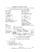
Section 4 Theory of Operation Platinum VAX-C Series AC1 AC2 GND AC AC Line Filter +12VIN DC 5V Vs DC +12V,12.5A Cr DC 12V,0.25A DC1 DC 6 12V +5V DC +5V,12A 3 Cells Li Ion 10.8V nom. 1.2AHr 13WHr 20Apk DC2 DC 6 12V 1.5A Vbat 6 10.8V Qa n +24VM DC +24V,1.2A DC3 DC 6 12V Qb Qc +24V p DC +12V,3.5A n 12V n +12V Qd +12VOSC Ideal Diode Data Line 32 Mins Timers & Driver 1 Min Figure 4-3 Low Voltage Power Supply Block Diagram 4.4.
Section 4 Theory of Operation Platinum VAX-C Series the +24V, +12V, +12Vosc, +5V, and -12V power supply interface board dc outputs energized for one minute following a power failure. During this time the PA assembly is not powered. • It keeps the oscillator circuits and the internal GPS receiver operating for an additional fifteen minutes following the one minute modulator controller backup operation. It accomplishes this by de-energizing all but the +12Vosc power supply outputs.
Platinum VAX-C Series 4.4.6 Section 4 Theory of Operation ASI / SMPTE 310 Inputs / Output The modulator FPGA decodes the four ASI inputs and modulates the active input stream with the selected standard. Transformers are used on the input of the ASI data to improve the rejection of common mode interference on the input cables. Cable equalization circuitry is also used. The ASI inputs to the FPGA are at LVDS levels. Input choices are shown below, rear panel connectors are shown to the right.
Platinum VAX-C Series Section 4 Theory of Operation 4.4.7 PFRU (Precise Frequency Reference Unit) Board The Precise Frequency Reference Unit (board) performs four functions through four circuits. They are as follows: • • • • Provides an optional GPS receiver unit 10 MHz reference oscillator 1st LO PLL 2nd LO PLL 4.4.7.1 PFRU Board 1st LO PLL for the DAC Clock Circuit This PLL (Phase Lock Loop) oscillator provides a clock to the IF DAC (Digital to Analog Converter).
Section 4 Theory of Operation Platinum VAX-C Series Table 4-2 DAC Clock Frequencies Modulation ATSC DVB-T/H ISDB-T DMB-T NTSC/PAL DAB 54 MHz from Signal Processor Board 10 MHz Reference Input Reference From Ref. Osc. DAC Clock Freq. 430.489 MHz 438.857 MHz 445.823 MHz 453.600 MHz 436.800 MHz 409.600 MHz Frequency Divider and Phase Detector Low Pass Filter Offset Freq. 32.378 MHz 30.286 MHz 28.544 MHz 26.600 MHz 30.800 MHz 37.
Section 4 Theory of Operation 4.4.7.2 Platinum VAX-C Series PFRU Board Local Oscillator-2 Circuit, For UDC This circuit provides a local oscillator for the up/downconverter. It is used to heterodyne the IF signal to the on channel RF frequency in the upconverter and to heterodyne the RF sample back to the IF frequency in the downconverter. The phase noise specification for local oscillator 2 (the RF UDC PLL) is given in Table 4-3.
Section 4 Theory of Operation Platinum VAX-C Series Table 4-4 RF UDC PLL Frequencies Channel Frequency Range 168 to 242 MHz Band BIII Local Osc Frequency Range 168 to 242 MHz in 1Hz steps IF Frequency Order Inverted The IF and local oscillator frequencies will vary somewhat to accommodate the various modulation methods uses and the bandwidth of the output signal. Output signal bandwidth range is 5, 6, 7, or 8 MHz. The IF frequency tolerance of +/-0.
Platinum VAX-C Series Section 4 Theory of Operation Low Pass Filter FPGA and Phase Detector Low Pass Filter VCO Low Pass Filter J3, 10 MHz Output To Optional Repeater Receiver Card Coupler 10 MHz To RF UDC PLL J4-16, 1 PPS Reference Input From Ref. Osc. DAC Select 1 = 10 MHz 0 = 54 MHz D J6, 54 MHz Input Resistive DIvider Q Q 10 or 54 MHz To DAC PLL 54 MHz To Level Detector Figure 4-7 PFRU Board 10 MHz Reference Oscillator Circuit 4.4.7.
Section 4 Theory of Operation Platinum VAX-C Series 4.4.8.
Section 4 Theory of Operation Platinum VAX-C Series The signal is next sent to a two stage VHF tunable bandpass filter, which removes the undesired mixing products. In each filter stage, the filtered RF is buffered by a MMIC amplifier. After the filtering process the RF signal is applied to a mute circuit, which consists of a SPDT low-loss, high isolation (60dB @ 1.5GHz) microwave relay. When muted, the normal RF path is opened and the RF switched into a 50 load.
Section 4 Theory of Operation Platinum VAX-C Series SPDT NonReflective Switch J4, PA RF Sample SPDT NonReflective Switch J5, HPF RF Sample Downconverter Up Down Converter Top Board Switch 4.4.8.
Platinum VAX-C Series Section 4 Theory of Operation Down converter top board via J8 and is sent to J6 on the Up/Down converter base board. In the Up/Down converter base board, the filtered IF is buffered and variably attenuated to allow the controller to optimize the level into the A/D converter in the signal processing board. A high linearity output amplifier drives the IF output to the ADC. 4.4.8.5 LO Distribution LO (Local Oscillator) distribution is part of the up/downconverter.
Platinum VAX-C Series 4.5 Section 4 Theory of Operation VAX-C Transmitter PAs 4.5.0.1 Fault Protection Certain fault conditions warrant immediate, hardware-invoked shut-down of the power supply and RF Drive to provide rapid system protection.
Section 4 Theory of Operation Platinum VAX-C Series factors on a change of frequency and provide reasonable accuracy without requiring re-calibration. A full two-point calibration should be performed at first turn-on at mid-band (205 MHz). • On-board switching is performed so that the forward power sample will automatically be used as a signal source for reflected calibration.
Platinum VAX-C Series Section 5 Maintenance and Alignments 5 This section contains the maintenance and alignment procedures for the Platinum VAXC Series VHF transmitter. This includes routine maintenance, PA module replacement, PA module repair, transmitter calibration and PC Board replacement procedures. ! WARNING: THE SERVICE WORK DESCRIBED IN THIS SECTION MUST BE CARRIED OUT BY TRAINED STAFF ONLY. 5.
Section 5 Maintenance and Alignments 5.2 Platinum VAX-C Series PA Module Removal and Replacement ! CAUTION: TOXIC BERYLLIUM SOME COMPONENTS IN THE PA MODULE CONTAIN TOXIC BERYLLIUM. THIS LIMITS MODULE REPAIR TO A MODULAR LEVEL CONSISTING OF PALLETS AND PC BOARDS ONLY. HOT SURFACE PLATINUM PA MODULES ARE DESIGNED TO HANDLE VERY HIGH TEMPERATURES AND MAY BE EXTREMELY HOT, UP TO 58O F (32O C) ABOVE ROOM TEMPERATURE.
Platinum VAX-C Series ! Section 5 Maintenance and Alignments CAUTION: THE PA MODULE MAY BE HOT. ALLOW THE COMPONENTS TO COOL OR USE PROTECTIVE GLOVES TO PROTECT HANDS. STEP 3 See Figure 5-1. Remove the two screws from the rear panel on either side of the output connector. Figure 5-1 RF Output Connector STEP 4 Remove the PA module screw from the right side of the chassis. This screw threads into the L bracket attached to the PA module heat sink.
Section 5 Maintenance and Alignments Platinum VAX-C Series J3 Nut Figure 5-3 Amplifier Compartment ! STEP 5 Loosen the screw that holds the L bracket to the PA module heat sink and then rotate the L bracket 90o to allow maximum clearance during module removal. STEP 6 Remove the nut (Figure 5-3) that fastens the PA module bracket to the bottom of the chassis. CAUTION: DO NOT DAMAGE COMPONENTS ON PA INTERFACE BOARD WHEN INSTALLING THE PA MODULE FROM THE CHASSIS.
Platinum VAX-C Series 5/9/13 Section 5 Maintenance and Alignments STEP 11 Remove the W9 ribbon cable from the J6 connector on the PA interface board. STEP 12 Slide PA module toward front of chassis output until RF output connector clears the rear of the chassis. STEP 13 Lift the PA module partially out of the chassis (tip PA interface board upward). STEP 14 Disconnect ribbon cable W5 from J5 on the underside of the PA interface board (see Figure 5-3).
Section 5 Maintenance and Alignments 5.2.2 Platinum VAX-C Series PA Module Installation Required Tools: WAGO extractor tool #1 Phillips screw driver M7 (9/32") nut driver NOTE: Refer to Figure 5-3 on page 5-4 for location of components and connectors noted in the procedure below. The type of PA module may vary depending on transmitter model. PA and PS modules must be removed (or installed) with the transmitter turned off and unplugged. STEP 1 ! Turn off the transmitter and disconnect AC power.
Platinum VAX-C Series STEP 6 Slide PA module toward rear of chassis until RF output connector clears the rear of the chassis. STEP 7 Connect the W9 ribbon cable to the J6 connector on the PA interface board. STEP 8 Connect the W10 ribbon cable to J9 on the PA interface board. STEP 9 Use a WAGO tool to connect power supply wires 54 & 55 to TB1 on the interface board. STEP 10 Connect the two RF connectors J3 & J4 to the coupler ports. STEP 11 Connect the RF input cable J1 from PA module input port.
Section 5 Maintenance and Alignments 5.3 Platinum VAX-C Series PS Module Removal/Replacement Required Tools: Ohmmeter WAGO extractor tool #1 Phillips screw driver Isopropyl alcohol Heat sink compound or pad. Paper towel or cloth. STEP 1 ! Turn off the transmitter and disconnect AC power. WARNING: REMOVE AC POWER FROM THE VAX-C TRANSMITTER BEFORE ATTEMPTING PA MODULE REMOVAL. THERE ARE EXPOSED VOLTAGES IN THE PA SECTION THAT MAY CAUSE INJURY OR DAMAGE TO COMPONENTS IF CONTACTED.
Section 5 Maintenance and Alignments Platinum VAX-C Series Figure 5-4 PS Module 5/9/13 STEP 6 Use a Phillips screwdriver to remove the four screws (one in each corner) from the PS board. STEP 7 Lift the PS board and heatsink assembly up to remove them from the chassis. STEP 8 Gently lift upward on the PS assembly to separate it from the heat sink. STEP 9 Clean up the heat sink compound or pad residue on the heatsink. Use alcohol to remove completely.
Section 5 Maintenance and Alignments 5.4 Platinum VAX-C Series Power Calibrations NOTE: The following calibration procedures are for digital modes. Factory FWD/Rfld calibration has been performed during factory test at 205 MHz center frequency and the calibration is valid for the entire VHF band. Factory FWD/ Rfld calibration should be required only if a PA interface board, directional coupler, or sample cable is replaced.
Platinum VAX-C Series Figure 5-5 on left - System Calibration Section 5 Maintenance and Alignments on right - System Calibration options The procedures described below assume use of the VAX-C LCD menus screens. Power calibrations include: • Factory Fwd/Rfld - System forward and reflected power at output of transmitter before band pass filter (BPF). Typically performed at 205 MHz. • Field Fwd/Rfld - System forward power at output of transmitter before BPF.
Section 5 Maintenance and Alignments Platinum VAX-C Series Reflected Port Forward Port RF Out RF In Figure 5-6 Typical Output Directional Coupler and Connections 5.4.1 System Factory Fwd/Rfld Calibration System factory forward power is calibrated over a range of 10 dB below model power to full model power. The forward power reference sample is taken from the internal directional coupler and regulates the power of the transmitter output before any filter losses.
Platinum VAX-C Series ! Section 5 Maintenance and Alignments CAUTION: DO NOT APPLY EXCESSIVE DOWNWARD PRESSURE (WEIGHT) ON THE TYPE N OUTPUT CONNECTOR. IF A DIRECTIONAL COUPLER IS ATTACHED DIRECTLY TO THE OUTPUT CONNECTOR IT SHOULD BE ADEQUATELY SUPPORTED. EXCESSIVE STRESS ON THE CONNECTOR MAY CAUSE INTERNAL DAMAGE AND RESULT IN HIGH VSWR CONDITIONS THAT COULD CAUSE ARCING OR HEATING.
Section 5 Maintenance and Alignments Platinum VAX-C Series FACTORY FWD/RFLD. Press Enter one time to highlight the menu then use the up/down keys to select Factory Fwd/Rfld. STEP 11 Start the calibration procedure by pressing the Enter button again. STEP 12 Follow the instructions on the LCD screen and use the power Raise/ Lower buttons to adjust the transmitter output to the desired low level.When a stable reading is attained on the power meter, select Save and then press Enter.
Platinum VAX-C Series ! Section 5 Maintenance and Alignments STEP 1 Zero and calibrate the RMS power meter, following the manufacturer’s procedures for that specific model. STEP 2 Install a directional coupler at the output of the transmitter. The directional coupler must be capable of handling the rated transmitter output power and have defined coupling values to allow accurate measurements of forward power levels.
Section 5 Maintenance and Alignments Platinum VAX-C Series STEP 9 Press the transmitter ON button while monitoring transmitter forward power on the external power meter. Monitor reflected power on the LCD screen. Slowly raise the power to the desired operational power level and allow the transmitter to run for several minutes until output power is stable. STEP 10 Compare the external power meter value with the forward power displayed on the LCD screen.
Platinum VAX-C Series 5.5 Section 5 Maintenance and Alignments Pre-correction for Digital TV & DAB Digital transmitters are typically operated in adaptive nonlinear predistortion and linear equalization mode. The precorrection and equalization are applied in the modulator section (exciter). The procedure described below will automatically calculate the precorrection for an installed system. Once the precorrection has been calculated, it can be stored in the setup memory for later use in Stored mode.
Section 5 Maintenance and Alignments Platinum VAX-C Series NOTE: If the Linear RTAC section is in BYPASS at this time, linear correction will not be stored. Linear Equalizer: STEP 5 Set the linear RTAC mode to ADAPT via the POWER menu on the VAX-C front panel LCD display or by using the VAX-C web browser to navigate to Exciter Home > Setup > DUC/RTAC screen. STEP 6 Verify that the linear RTAC attempt and success counters increment about every twenty seconds.
Platinum VAX-C Series Section 5 Maintenance and Alignments Figure 5-7 RTAC Stored Correction Sets Screen STEP 2 Enter a name of up to sixteen characters for the desired set. STEP 3 Press the SAVE button to store the correction to memory. NOTE: The correction currently being applied will be stored, overwriting any values previously stored in memory. 5/9/13 888-2857-001 WARNING: Disconnect primary power prior to servicing.
Section 5 Maintenance and Alignments 5.6 Platinum VAX-C Series Changing Frequency This procedure describes manual change of the channel frequency to a new value. Save the settings on the initial channel before proceeding with frequency change. Once operation on the new frequency has been established, a second set of settings should also be saved. This will greatly facilitate changing between frequencies in the future by simply duplicating the previously recorded settings.
Platinum VAX-C Series STEP 3 ! Section 5 Maintenance and Alignments Tune output filter (if present) to new frequency. Consult filter test data, specification sheet, or other manufacturer-supplied information for more details. Some output filters are band limited and may not be adjustable across the VHF band. In cases where the filters are band limited a replacement filter will be required. WARNING: HARRIS DOES NOT RECOMMEND FIELD TUNING OF FILTERS.
Section 5 Maintenance and Alignments 5-22 Platinum VAX-C Series STEP 10 Slowly raise the transmitter power (using the raise button) until the desired power reading is observed on calibrated power meter connected to directional coupler at transmitter output (or at the front panel on some models). STEP 11 Navigate to the SETUP>XMTR POWER SETTINGS>POWER CALIBRATION MENU. Select FIELD FWD/RFLD and perform calibration.
Section 5 Maintenance and Alignments Platinum VAX-C Series 5.7 Fan Replacement There are two 12Vdc fans on the front of the Platinum VAX-C. The fans can be replaced while the transmitter is on air. STEP 1 Loosen the two screws that attach the VAX-C front panel to the chassis. STEP 2 Remove the front cover to expose the two fan assemblies. Figure 5-8 VAX-C Fan Connection STEP 3 ! Unplug the connectors that supply DC to the fan. The unplugged connectors are shown in Figure 5-8.
Section 5 Maintenance and Alignments 5.8 Platinum VAX-C Series Air Filter Replacement Monthly inspection and cleaning of the air filter is recommended. Clean filters more often in dusty environments. The filters can be easily removed from the front panels and then cleaned. The filter must be thoroughly dry before reuse. The part number for the filter material used in the VAX-C is 061-0115-000. The filter material is 1/4" thick, 10ppi.
Platinum VAX-C Series 5.9 Section 5 Maintenance and Alignments Cleaning Occasionally the VAX-C circuit boards should be cleaned. All precautions against static should be observed. The technician should be grounded, either through conductive shoes or through a static ground strap. The VAX-C should be powered down and disconnected from AC mains power before the cleaning process is started. A vacuum cleaner should be used to remove dust from the assemblies.
Platinum VAX-C Series Section 5 Maintenance and Alignments 5.10 Changing Date and Time Battery STEP 1 Remove power from the VAX-C. STEP 2 If the VAX-C is installed in a rack, remove it and place on bench. STEP 3 Remove the top cover. STEP 4 Remove the old battery and insert a new battery with positive side toward clip.Battery slides out from under the clip. See Figure 5-10 for battery location. NOTE: Dispose of battery properly. Follow applicable local regulations.
Platinum VAX-C Series Section 5 Maintenance and Alignments 5.10.1 Setting VAX-C Date and Time The VAX-C date and time should be set after the date and time battery is installed. The date/time can be set using either the web browser or the LCD screen and control buttons. Use the following procedure to set the date and time using the web browser. STEP 1 Use the web browser to log into the VAX-C using the front or rear ethernet connectors.
Section 5 Maintenance and Alignments Platinum VAX-C Series Battery Backup Figure 5-11 Battery Backup (UPS) Location The optional battery backup kit 9710051012G includes: • • Qty 4, 3020803006, Screw, Mach M3-0.5 X 6 SEMS Qty 1, 6600179000, PWA, 9.6V Battery Pack Instructions: ! STEP 1 Turn off transmitter. STEP 2 Disconnect AC mains power from the VAX-C chassis. WARNING: REMOVE ALL POWER TO THE VAX-C BEFORE PERFORMING THE FOLLOWING PROCEDURE.
Platinum VAX-C Series Section 5 Maintenance and Alignments straight slot screwdriver. Remove the VAX-C front cover and remove the four Phillips screws that hold the VAX-C in the rack. Slide the VAXC out of the rack and place it on a sturdy table or bench. STEP 4 Remove the four Phillips screws on the top, rear of the VAX-C that secure the cover chassis. Remove the cover by sliding it toward the rear of the VAX-C and lifting it upward.
Section 5 Maintenance and Alignments Platinum VAX-C Series In order to purchase a new feature key the user must provide Harris with the front MAC address from the VAX-C(s) being updated. The front MAC address can be found on the Remote Communications web browser GUI screen shown in Figure 3-22 on page 3-37. The new feature key is activated after the VAX-C transmitter is rebooted.
Platinum VAX-C Series Section 5 Maintenance and Alignments 5.12 Connecting To The VAX-C This section describes connection to the VAX-C with a PC (Windows XP operating system) via ethernet for setup, operation, and software downloads. NOTE: Harris recommends the Firefox browser for use with this transmitter but Internet Explorer version 8.0 or later can also be used. Use of IE version 8.0 or higher may require a change in the IE8 Compatibility View Settings screen.
Section 5 Maintenance and Alignments Platinum VAX-C Series VAX-C front ethernet port to the computer. For additional information see "5.12.4 Connection Via Front Ethernet Connector" on page 5-34. ! CAUTION: DO NOT CONNECT THE VAX-C’S FRONT RJ45 CONNECTOR TO A NETWORK BECAUSE THE DHCP SERVER IN THE VAX-C WILL CONFLICT WITH THE DHCP SERVER IN THE NETWORK. The rear RJ45 connector - VAX-C rear RJ45 Ethernet connector can operate in the DHCP client mode or with a static IP.
Section 5 Maintenance and Alignments Platinum VAX-C Series Table 5-1 Default Passwords User Level Username Password Engineer1 admin admin Engineer2 user2 pass2 Administrator netadmin harris Monitor - - 5.12.3 Changing Passwords VAX-C Usernames, Passwords and Session Time Out duration can be changed using the Tx Home>Exciter Home>Setup>User Settings>Active User screen. Login to the VAX-C using the netadmin username and password is required to access the User Management screen.
Section 5 Maintenance and Alignments Figure 5-13 NetAdmin Active Users Screen Platinum VAX-C Series NetAdmin - User Management Screen Once the desired changes have been made to the NetAdmin-User Management screen press the Active button to return to the Active users screen where the current connection information is provided. Access to other screens is not allowed while logged in as an administrator. If access to other screens is desired the user must Logout and then Login as an engineer. 5.12.
Section 5 Maintenance and Alignments Platinum VAX-C Series 5.12.4.1 Assigning Computer IP Address in DHCP Client Mode If the computer is in the DHCP client mode, it will automatically obtain an address from the front panel RJ45 (Ethernet) connector. Use the following procedure to obtain an address for the computer. To avoid reboot of the computer refer to Section 5.12.4.2 for an alternate method.
Section 5 Maintenance and Alignments Platinum VAX-C Series a. The new IP computer ethernet address should be set. STEP 9 Connect to the VAX-C using the procedure in 5.12.4.3 . To reconnect to another Ethernet network, connect the computer to the desired network and perform either of the above procedures. 5.12.4.3 Making the Connection to the VAX-C STEP 1 Connect an ethernet cable between the computer’s RJ45 connector and the VAX-C front panel RJ45 connector. a.
Platinum VAX-C Series STEP 3 Section 5 Maintenance and Alignments The Ethernet #1 window gives the front Ethernet parameters. 5.12.5 Connecting Via VAX-C Rear Panel Ethernet Connector Two methods are used to connect to the rear panel RJ45 connector, they are as follows: • • Connecting through an existing ethernet network. Direct connection, computer to VAX-C rear RJ45 connector. Both of these connection methods are described below. 5.12.5.
Section 5 Maintenance and Alignments Platinum VAX-C Series 5.12.5.2 Direct Connection, Computer To VAX-C Rear Ethernet Connector Direct connection to the VAX-C’s rear RJ45 connector is not recommended, but it can be done. The front panel, with its DHCP server is recommended for direct connection.
Section 5 Maintenance and Alignments Platinum VAX-C Series STEP 5 In the local area connection properties window, scroll down in the sub window until the Internet Protocol (TCP/IP) selection appears. STEP 6 Click on the Internet Protocol (TCP/IP) selection. STEP 7 Click on the Properties soft key below and to the right of the sub window. STEP 8 The Internet Protocol (TCP/IP) Properties window will appear. STEP 9 In this window, two choices appear, they are: a. Obtain an IP address automatically.
Section 5 Maintenance and Alignments Platinum VAX-C Series a. The present computer IP address and other information will appear. 5.12.6.2 VAX-C Screen Captures VAX-C GUI screens can easily be captured using the Alt - Print Screen keys. The procedure is as follows. STEP 1 Connect a computer to the VAX-C. STEP 2 Select the screen to be captured. STEP 3 Press and hold the Alt key while pressing the print screen key. a. Earlier Windows programs copied the captured screen to the clipboard. b.
Platinum VAX-C Series Section 5 Maintenance and Alignments 5.13 Updating VAX-C Software The latest revision of VAX-C software is available at the Harris Broadcast Customer Portal web site. NOTE: The transmitter will go off-air during software updates. NOTE: If changing modulation type, enter a new ’feature key’ before programming. NOTE: Should this procedure result in a crashed or incomplete software download/ update, refer to 5.14 on page 5-48, ’Bootloader Recovery Procedure’.
Section 5 Maintenance and Alignments Platinum VAX-C Series Figure 5-14 VAX-C Login Screen STEP 3 Press the Exciter Home soft key on the Xmtr Home page. STEP 4 Press the Setup soft key on the Exciter Home page. STEP 5 Press the ISP soft key on the right side of the Setup page.The In System Programming screen, shown in Figure 5-15, will be displayed. Figure 5-15 VAX-C In-System Programming Screen 5-42 888-2857-001 WARNING: Disconnect primary power prior to servicing.
Platinum VAX-C Series STEP 6 Section 5 Maintenance and Alignments Press the Browse soft button to the right of the file to upload box on the In-System Programming screen. This will bring up the File Upload sub window, shown in Figure 5-16. Figure 5-16 File Upload Window STEP 7 From the File Upload sub window, locate the software file to be downloaded (.s19 file extension). This is the file which was previously down loaded and saved to the computer. When the correct file has been highlighted, press Open.
Section 5 Maintenance and Alignments Platinum VAX-C Series Figure 5-17 In-System Programming Window STEP 10 The screen shown in Figure 5-18 will appear. Select OK to continue with programming. Figure 5-18 Are You Sure Window 5-44 888-2857-001 WARNING: Disconnect primary power prior to servicing.
Section 5 Maintenance and Alignments Platinum VAX-C Series Figure 5-19 Programming Screen STEP 11 STEP 12 The screen shown in Figure 5-19 will appear indicating that programming has begun. This process will take several minutes. Once programming is complete the web connection to the VAX-C will be broken and communication with the VAX-C will cease (a yellow error screen will be displayed). When communications is reestablished a login screen will open.
Section 5 Maintenance and Alignments Platinum VAX-C Series 5.13.1 Saving and Recalling Settings The Save Settings soft key can be used to save a copy of the current user settings stored in EEPROM in the VAX-C. All settings with the exception of the front and rear MAC addresses and feature key, are included. These stored settings can be used to restore a system to known user settings.
Platinum VAX-C Series Section 5 Maintenance and Alignments Figure 5-21 In order to restore the settings that are saved in the file, follow the process described in "5.13 Updating VAX-C Software" on page 5-41. Use the .s19 file saved in the previous step as the file to upload. 5.13.2 Web Browser Screen Captures Web browser GUI screens can easily be captured using the Alt - Print Screen keys. The procedure is as follows. STEP 1 Connect a computer to the VAX-C. STEP 2 Select the screen to be captured.
Section 5 Maintenance and Alignments Platinum VAX-C Series 5.14 Bootloader Recovery Procedure Recovery from a crashed or incomplete ISP (In-System Programming) download (software update) by invoking the bootloader. In most cases this can be accomplished using the following procedure: STEP 1 Connect to the front Ethernet port using instructions in Section 5.12.4. STEP 2 Open a web browser session via the VAX-C front Ethernet port by entering 192.168.117.88/isp in the navigation box.
Section 5 Maintenance and Alignments Platinum VAX-C Series Figure 5-23 Bootloader Browse Screen STEP 4 Highlight the desired file then press Open. STEP 5 The bootloader ISP screen will be displayed and the ’File to Update:’ window will display the filename. Press ’Submit’. The update will take several minutes. Do not disrupt the process. STEP 6 Upon completion of the process open a web browser session to reestablish the connection to the VAX-C transmitter. STEP 7 End of procedure.
Section 5 Maintenance and Alignments Platinum VAX-C Series Figure 5-24 Ethernet Downloader Screen STEP 4 Double strike the enter key to bring up the basic Ethernet screen. Figure 5-25 Tera Term Ethernet Screen STEP 5 5-50 Use the static IP from the front panel or network settings of the rear IP port that may have been previously configured. Open a web browser and type in the appropriate IP address. The In-System Programming (ISP) screen will appear.
Platinum VAX-C Series 5/9/13 Section 5 Maintenance and Alignments STEP 6 Proceed to load the complete *.s19 file. STEP 7 End of procedure. 888-2857-001 WARNING: Disconnect primary power prior to servicing.
Section 5 Maintenance and Alignments Platinum VAX-C Series 5.15 Connecting to the VAX via SNMP The VAX-C transmitter family supports monitoring and alarming functionality via SNMP (Simple Network Management Protocol). Basic control of the equipment is possible after activation in the equipment. SNMP versions V1 and V2c and V3 are implemented. This section assumes a good working knowledge of networking and SNMP connectivity.
Platinum VAX-C Series Section 5 Maintenance and Alignments 5.15.2 Supported MIBs As of this printing, the Harris VAX transmitter can serve out three different MIBs: • • • Harris transmitter base MIB (basic functionality for all Harris transmitters) IRT DVB Single Transmitter MIB IRT DAB Single Transmitter MIB 5.15.3 Harris Base MIB Description The Harris base MIB is usable in all NMS (Network Management Systems) and is provided in text-format.
Section 5 Maintenance and Alignments Platinum VAX-C Series 5.15.5 Harris SMI (Structure of Managed Information) Harris Transmission SMI Harris Transmitters branch OID: 1.3.6.1.4.1.290.9.2.1 iso(1).org(3).dod(6).internet(1).private(4).enterprises(1).harris(290).bcd2(9).transmissi on(2) Figure 5-27 Harris SMI Block Diagram 5-54 888-2857-001 WARNING: Disconnect primary power prior to servicing.
Platinum VAX-C Series Section 5 Maintenance and Alignments Figure 5-28 MIB 2 Description 5/9/13 888-2857-001 WARNING: Disconnect primary power prior to servicing.
Section 5 Maintenance and Alignments Platinum VAX-C Series 5.16 DAB Single Frequency Network (SFN) Setup A popular option for DAB/ T-DMB implementation is the single frequency network (SFN). In a single frequency network, all transmitters in a geographic region are synchronized in frequency and modulation content (symbol). For such a system to work, two parameters must be tightly controlled at the transmitter site: the RF centerchannel frequency and the program modulation (symbol) delay.
Section 5 Maintenance and Alignments Platinum VAX-C Series Static delay is sometimes known as “Transmitter Trimming Delay” 5.16.
Section 5 Maintenance and Alignments Platinum VAX-C Series 5.17 DAB EDI/IP Input Option NOTE: The DAB EDI/IP board (9810274009G) consists of the MCF5484 UC Module (9010213011G) added to the DAB ETI Input Option (9810274012G). The original ETI input board (9010215291G) is part of the 9810274012G. Figure 5-30 Assembly DAB EDI/IP Inuput Option 5.17.
Platinum VAX-C Series Section 5 Maintenance and Alignments 5.17.3 Inputs/Outputs • • • • Two ETI, BNC, 75 ohm, female inputs - labeled ETI1 IN and ETI2 IN One ETI, BNC, 75 ohm, female output - labeled ETI MON Two 10/100 BaseT network, RJ45 ports on the rear panel - labeled ETH1 and ETH2 Three SMA, 50 ohm, female outputs - labeled 2.048 MHz-Out, SYNC ETI Out, & SYNC OFDM Out 5.17.4 Operation One EDI stream can be processed by the EDI board along with one ETI stream.
Section 5 Maintenance and Alignments Platinum VAX-C Series 5.17.6 GUI Screens Figure 5-32 EDI Setup Screens Setup screens can be accessed by using the M2X, LPU or VAX-C GUI interface and navigating to Exciter Home>Setup>DAB Modulator>EDI. Figure 5-33 DAB Setup Screen and EDIStatus Screen 5.17.7 References Technical Specification, ETSI TS 102 xxx V1.1.1 (2008-10-21) Digital Audio Broadcasting (DAB); Encapsulation of DAB Interfaces (EDI) 5.17.
Platinum VAX-C Series Section 5 Maintenance and Alignments "EDI_BETA_VERSION_0x0036.s19". Hit Submit, after a minute you should see the "Program" button, select it. The EDI board will reboot after programming. 5/9/13 888-2857-001 WARNING: Disconnect primary power prior to servicing.
Section 5 Maintenance and Alignments Platinum VAX-C Series 5.18 Typical Test Equipment Table 5-2 Recommended Test Equipment Equipment Type TV Spectrum Analyzer Manufacturer R&S Demodulator Spectrum Analyzer Power measurement Frequency measurement R&S Agilent Agilent Agilent Miscellaneous Test Equipment Bird Narda Eagle Eagle Fluke Myat Dielectric Myat Optional Adapters and connectors Adapters and connectors Attenuator 5-62 Model Number ETL Harris Part No.
Section 5 Maintenance and Alignments Platinum VAX-C Series Table 5-3 DAB Test Equipment Equipment Type Spectrum Analyzer Network Analyzer Notch Filter Manufacturer R&S/Agilent R&S/Agilent Eagle Oscilloscope Multimeter Tektronix Fluke Power Meter R&S/Agilent GPS Antenna GPS Time Reference Frequency measurement Panasonic Harris Agilent Miscellaneous Test Equipment Reject Loads Directional Coupler Bridge Notch Filter Bird Useful Adapters and connectors /Bird Narda Eagle Eagle Myat Dielectric Mya
Section 5 Maintenance and Alignments Table 5-3 Equipment Type Adapters and connectors Attenuator 5-64 Platinum VAX-C Series DAB Test Equipment Manufacturer Model Number Options Type N to BNC, male to female Type N to BNC, female to male BNC barrel, female to female BNC barrel, male to male SMA to BNC, male to female SMA to N, male to female SMB (push on) to BNC SMC to BNC, screw on jack to plug BNC to TNC, jack to plug BNC to TNC, jack to jack TNC to N, plug to jack TNC to N, jack to plug 10 dB atten
Platinum VAX-C Series 6 Section 6 Diagnostics 6.1 Introduction This section contains diagnostic and troubleshooting information for the VAX-C series VHF transmitter. Included is a complete description of all faults which can be displayed via the transmitter front panel LCD, Web Interface or TCU (transmitter control unit GUI (Graphical User Interface).
Section 6 Diagnostics Platinum VAX-C Series web browser and see what faults have occurred and in what order. If you are not familiar with web browser navigation, refer to Section 3.1 Transmitter Control and to 6.2 Web Browser Fault Log below. The fault log on the LCD (in Status menu) will also give detailed fault information but is smaller and will take longer to read, as it only shows 4 faults per page. If the fault information is more than 11 characters, the description will be truncated.
Platinum VAX-C Series Section 6 Diagnostics NOTE: Tables 6-1 and 6-2 list VAX-C transmitter faults. They also give a brief description of each fault, the trip point and the transmitter action to take in response to the fault. Figure 6-1 on left - All Faults Log Screen 5/9/13 on right - Active Faults Log Screen 888-2857-001 WARNING: Disconnect primary power prior to servicing.
Platinum VAX-C Series Section 6 Diagnostics 6.3 Fault Tables The following tables provide a listing of VAX-C Transmitter faults along with a brief description, the fault level or threshold and the action taken by the transmitter. Table 6-1 UDC Faults Nominal Value/ Scaling Trip Level Mute LED red. System and Mute LEDs red. 1000mV +/100mV, detector referenced to mixer input level. 900mV NOTE: Test tone levels have not been characterized for any special considerations.
Section 6 Diagnostics Platinum VAX-C Series Table 6-2 MODFPGA Faults Fault Log Message Fault Description Front Panel LEDs Nominal Value/ Scaling Trip Level Modulator 25MHz Clock Indicates 25 MHz clock is present in MOD FPGA System and Mute LEDs red. 25 MHz clock edges are detected 25 MHz clock edges are not detected Modulator 54MHz Clock Indicates 54 MHz clock is present in MOD FPGA System and Mute LEDs red.
Platinum VAX-C Series Section 6 Diagnostics Table 6-3 MODFPGA Modulation Specific Faults Fault Log Message Fault Description Front Panel LEDs Nominal Value/ Scaling ASI 2 LP Error on ASI 2 LP in MOD FPGA for DVB System LED red. No errors Input present: Uncorrected byte errors, Corrected byte errors, Buffer overflow Input not present: Hierarchy mode AND ERRW_MODFPGA_PRBS_ON =false Modulator Illegal Config Mute Indicates illegal DVB configuration parameters in MOD FPGA System and Mute LEDs red.
Section 6 Diagnostics Platinum VAX-C Series Table 6-3 MODFPGA Modulation Specific Faults Nominal Value/ Scaling Trip Level Fault Log Message Fault Description Front Panel LEDs Modulator Input D Indicates input D is present in MOD FPGA. ATSC SMPTE B System LED red. TS Input LED yellow or red. MPEG sync indicator = 1 MPEG sync indicator = 0 AND input D selected for primary or auxiliary input Modulator Input Signal Loss Indicates required inputs are not present in MOD FPGA.
Platinum VAX-C Series Section 6 Diagnostics Table 6-3 MODFPGA Modulation Specific Faults Nominal Value/ Scaling Trip Level System LED red. Timestamp is present Input is present, but timestamp is missing on input 1 Indicates timestamp is missing on valid input 2 System LED red. Timestamp is present Input is present, but timestamp is missing on input 2 Modulator PFRU Undisciplined Indicates PFRU PLL is not disciplined for DAB System LED red.
Section 6 Diagnostics Platinum VAX-C Series Table 6-3 MODFPGA Modulation Specific Faults Nominal Value/ Scaling Trip Level Fault Log Message Fault Description Front Panel LEDs Modulator Input D Indicates input D is present in MOD FPGA. ATSC SMPTE B System LED red. TS Input LED yellow or red. MPEG sync indicator = 1 MPEG sync indicator = 0 AND input D selected for primary or auxiliary input Modulator Input Signal Loss Indicates required inputs are not present in MOD FPGA.
Platinum VAX-C Series Section 6 Diagnostics Table 6-3 MODFPGA Modulation Specific Faults Nominal Value/ Scaling Trip Level Fault Log Message Fault Description Front Panel LEDs Modulator Input C Indicates input C is present in MOD FPGA. ATSC ASI LPB System LED red. TS Input LED yellow or red. MPEG sync indicator = 1 MPEG sync indicator = 0 AND input C selected for primary or auxiliary input Modulator Input B Indicates input B is present in MOD FPGA. ATSC SMPTE A System LED red.
Section 6 Diagnostics Platinum VAX-C Series Table 6-4 EXT I/O & DUC Faults Nominal Value/ Scaling Fault Log Message Fault Description Front Panel LEDs Digital Upconvertor Temperature Indicates digital upconverter FPGA is over temperature System and Mute LEDs red. Over temperature less than 4 times. 85 C limit. Over temperature 4 times (no time limit). 85 C limit Digital Upconvertor Input Signal Zero DUC input signal level is very low System and Mute LEDs red. RMS of signal greater than 0.
Platinum VAX-C Series Section 6 Diagnostics Table 6-6 PFRU Faults Fault Log Message Fault Description Front Panel LEDs Nominal Value/ Scaling Trip Level Frequency Ref. Not Alive Indicates PFRU is in known good state System and Mute LEDs red. Data pattern written/ read over HPI matches and board ID is correct Data pattern written/ read over HPI does not match or board ID is not correct Frequency Ref. External 1PPS External 1 pps is not present when it is required System and Mute LEDs red.
Section 6 Diagnostics Platinum VAX-C Series Table 6-7 MCU & SYS Faults Fault Description Front Panel LEDs Nominal Value/ Scaling Trip Level Warning when number of copies of application code is exceeded System LED orange. Copies < 105 Copies > 105 SYSTEM +1.4VDC Fault if over voltage System LED red. +1.4 V DC 10% above nominal SYSTEM +1.4VDC Fault if under voltage System LED red. +1.4 V DC 10% below nominal SYSTEM +3.3VDC Fault if over voltage System LED red. +3.
Platinum VAX-C Series Section 6 Diagnostics Table 6-7 MCU & SYS Faults Nominal Value/ Scaling Trip Level All status LEDs red. Modulation type read from modulator FPGA matches feature key Modulation type read from modulator FPGA does not match feature key System is VAX or VAX, but feature key is not correct All status LEDs red. System is VAX or VAX, and feature key is correct Micron Front Panel detected, but VAX or VAX is not enabled in feature key.
Section 6 Diagnostics Platinum VAX-C Series Table 6-7 MCU & SYS Faults Fault Log Message Fault Description Front Panel LEDs Nominal Value/ Scaling Trip Level SYSTEM Foldback active Power fold back warning System LED orange. Power foldback = 0 Power foldback > 0 SYSTEM Temporary Feature Key Installed Test Feature enabled in Feature Key. Feature Key will last for 24 hours, when 24 hrs elapses, Invalid Modulation Feature Fault will be activated. System LED orange.
Platinum VAX-C Series Section 6 Diagnostics Table 6-8 PA Faults Nominal Value/ Scaling Trip Level Fault Log Message Fault Description Front Panel LEDs PA Thermal Shutdown PA Hardware Thermal Shutdown Fault Drive Chain LED red. < 80.0 C Approximately 86 C trip point PA Overvoltage Fault PA Overvoltage Fault Drive Chain LED red. 43-47V 51V trip point PA FET 1 Overcurrent Fault PA Overcurrent Fault on FET 1 Drive Chain LED red.
Section 6 Diagnostics Platinum VAX-C Series Table 6-8 PA Faults Fault Log Message Fault Description Front Panel LEDs Nominal Value/ Scaling Trip Level PA Temperature Warning PA Temperature Warning Drive Chain LED orange. PA 1 and PA 2 Temp < 80.0 C 80.0 C <= PA 1 or PA 2 Temp < 85.0 C RF Input Level Low Warning RF Input Level Low Drive Chain LED orange.
Section 6 Diagnostics 6-18 Platinum VAX-C Series 888-2857-001 WARNING: Disconnect primary power prior to servicing.
Platinum VAX-C Series 7 Section 7 Parts List 7.
Platinum VAX-C Series Section 7 Parts List Table 7-1 FORMAT, XMTR, PLATINUM, VAX CC, 5W-250W - 995 0337 001 ((C)) Harris PN 620 3014 000 628 0024 000 634 0424 000 646 1355 000 880 0068 001 943 5602 592 952 9265 036 952 9265 037 952 9265 038 952 9265 039 9710035030G 9710035031G 9710051011G 9710051012G 9710051032GT 9710051033G 9710051037G 9710051038G 9710051039G 9710051040G 9710051041G 9710051043G 971 0051 050 9810031023G 9810031027G 981 0090 094 9810126014G 9810126016G 9810126113G 9810126115G 981 0155 001
Section 7 Parts List Platinum VAX-C Series Table 7-5 KIT, MPH OPTION - 9710051039G (A) Harris PN 861 1153 032 9710035014G Description SW/FW ATSC COMPLETE APP ASM-SUB-BLANK PANEL B Harris PN 861 1153 072 9710035014G Description SW/FW CTTB COMPLETE APP ASM-SUB-BLANK PANEL B Harris PN 861 1153 062 9710035014G Description SW/FW ISDB-T COMPLETE APP ASM-SUB-BLANK PANEL B Harris PN 302 0803 006 861 1153 082 9010215281G 9710035014G Description SCREW, MACH M3-0.
Platinum VAX-C Series Section 7 Parts List 943 5567 060 943 5567 061 943 5567 320 943 5567 514 943 5567 928 INDUCTOR, SERIES INDUCTOR, SHUNT COIL, 1-1/2 TURNS BALUN, BAND III ASSY, COIL 1-1/2 TURNS Table 7-11 1 EA 1 EA 1 EA 2 EA 1 EA PWA, BIII PA 881/E5600 SMT & BASIC THRU - 901 0230 052 (B) Harris PN 000 0000 010 358 2997 000 381 0029 000 383 0218 000 383 0277 001 383 0678 000 383 0817 000 383 0823 000 Description B/M NOTE: END PLATE, GREY (236) N-MOSFET, 2N7002 IC, MIC1555 (SOT23-5) IC LM4040CIM3-4
Section 7 Parts List Platinum VAX-C Series 519 0202 111 519 0202 119 519 0208 102 523 0003 101 523 0070 210 523 0070 217 545 0308 301 545 0308 306 545 0308 323 545 0308 414 545 0308 510 545 0309 301 545 0309 408 545 0309 601 545 0309 999 545 0310 019 545 0310 307 545 0310 801 545 0310 925 545 0327 000 545 0331 201 545 0331 318 545 0331 523 545 0331 601 545 0331 999 545 0369 101 545 0369 109 545 0369 201 CAP RF CHIP 27PF 1% 250V CAP RF CHIP 56PF 1% 250V CAP RF CHIP 11PF 2% 500V CAP 10UF 35V 20% SMT CAP 220
Platinum VAX-C Series Section 7 Parts List Table 7-12 Harris PN 843 5613 084 952 9265 002 952 9265 022 952 9265 023 CABLE PACKAGE, PA COMPLETE - 952 9265 033 (B) Description CABLE DIAGRAMS, ORION CABLE PACKAGE, PA CABLE #21 CABLE #22 Qty UM 0 DWG 1 EA 1 EA 1 EA Reference Designators Table 7-13 KIT, GPS ANT & CBL TNC TO SMA - 981 0090 094 (B) Harris PN 742 0020 000 742 0171 000 917 2573 048 Description ANTENNA, GPS PANASONIC CCAH32ST01 KIT, GPS ANT MOUNTING CABLE, GPS 50 OHM TNC:SMA 100FT Harris PN 7
Section 7 Parts List Platinum VAX-C Series 9710051018G *PWA, UAX CC 6800 INTERFACE (TOP LEVEL) 9810126013GWI WI, SRD/SRZ SATELLITE RECEIVER, ORION 1 EA 0 DWG Table 7-18 XMTR, PLATINUM, BASIC, COMPACT CLASS VHF - 981 0155 001 (A) Harris PN Description 053 0016 000 CARTON, TRIPLE WALL, 28X25X10.5 302 0803 008 SCREW, MACH M3-0.5 X 8 SEMS 306 0028 000 LOCKNUT, TOOTHWASHER M4-0.7MM 356 0004 000 CABLE CLAMP, NYLON 0.
Platinum VAX-C Series Section 7 Parts List 943 5588 030 943 5588 059 943 5588 062 943 5613 004 943 5613 007 943 5613 009 943 5613 017 943 5613 022 943 5613 023 943 5613 029 943 5613 036 943 5613 041 952 9248 010 9710051011G 9710051032G 9710051035G BLOCK-MOUNTING-PCA_UEP RAMP.
Section 7 Parts List Platinum VAX-C Series 612 2342 000 612 2347 000 RECP, 80C, RT-ANG, BD-BD RECP, MCX FEMALE 50 OHMS 2 EA 10 EA 620 2930 000 626 0005 000 646 2110 000 660 0054 000 801 0215 181 9010215182G 9306-0014 RECEPTACLE RT ANGLE BNC RECP, BNC, STACKED, THRU-PANEL, 50 OHM BARCODE, SN_ITEM_REV BATTERY 3V LITHIUM COIN CR2032 SCH, SIGNAL PROCESSING *PWA, SIGNAL PROCESSOR, SMT CONN HDR,2X7 POS .
Section 7 Parts List 7-10 Platinum VAX-C Series 888-2857-001 WARNING: Disconnect primary power prior to servicing.