
Instruction manual

Start
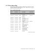
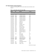
Address Size Register Access Discussed In
500 Models
1.E210.0000 32 bits Copy buffer register0 R/W
1.E210.0004 32 bits Copy buffer register1 R/W
1.E210.0008 32 bits Copy buffer register2 R/W
1.E210.000C 32 bits Copy buffer register3 R/W
1.E210.0010 32 bits Copy buffer register4 R/W
1.E210.0014 32 bits Copy buffer register5 R/W
1.E210.0018 32 bits Copy buffer register6 R/W
1.E210.001C 32 bits Copy buffer register7 R/W
1.E210.0020 32 bits Foreground R/W
1.E210.0024 32 bits Background R/W
1.E210.0028 32 bits PlaneMask R/W
1.E210.002C 32 bits PixelMask register R/W Section 6.4.4
1.E210.0030 3 bits Mode register R/W Section 6.4.1
1.E210.0034 4 bits Raster op register R/W Section 6.4.3
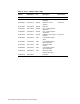
1.E210.0038 4 bits PixelShift register R/W Section 6.4.6
1.E210.003C 32 bits Address register R/W Section 6.4.7
1.E210.0040 32 bits Bresenham register 1 R/W Section 6.4.1
1.E210.0044 32 bits Bresenham register 2 R/W Section 6.4.1
1.E210.0048 32 bits Bresenham register 3 R Section 6.4.1
1.E210.004C BCont W Section 6.4.9
1.E210.0050 4 bits Deep register R/W Section 6.4.8
1.E210.0054 Start register W Section 6.4.9
1.E210.0058 Clear interrupt W Section 6.4.9
1.E210.0060 10 bits Video refresh counter R/W Section 6.4.10.1
1.E210.0064 28 bits Video horizontal setup R/W Section 6.4.10.3
1.E210.0068 28 bits Video vertical setup R/W Section 6.4.10.4
1.E210.006C 9 bits Video base address R/W Section 6.4.10.2
1.E210.0070 Video valid W Section 6.4.10
1.E210.0074 1 bit Enable/disable Interrupts W Section 6.4.9
1.E210.0078 8 bits TCCLK count R/W Section 6.4.11
1.E210.007C 10 bits VIDCLK count R/W Section 6.4.11
6–8 CXTurbo Graphics Subsystem: 300/500 Models