
Instruction manual
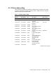

6.4 SFB ASIC Functions
Software setup of these registers controls the video and functional components of
the SFB ASIC. The following sections describe all registers and their format and
initialization state
Start
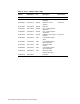
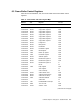
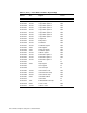
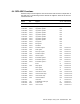
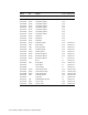
Address Size Register Access Discussed In
300 Models
1.C210.0000 32 bits Copy buffer register0 R/W
1.C210.0004 32 bits Copy buffer register1 R/W
1.C210.0008 32 bits Copy buffer register2 R/W
1.C210.000C 32 bits Copy buffer register3 R/W
1.C210.0010 32 bits Copy buffer register4 R/W
1.C210.0014 32 bits Copy buffer register5 R/W
1.C210.0018 32 bits Copy buffer register6 R/W
1.C210.001C 32 bits Copy buffer register7 R/W
1.C210.0020 32 bits Foreground R/W
1.C210.0024 32 bits Background R/W
1.C210.0028 32 bits PlaneMask R/W
1.C210.002C 32 bits PixelMask register R/W Section 6.4.4
1.C210.0030 3 bits Mode register R/W Section 6.4.1
1.C210.0034 4 bits Raster Op register R/W Section 6.4.3
1.C210.0038 4 bits PixelShift register R/W Section 6.4.6
1.C210.003C 32 bits Address register R/W Section 6.4.7
1.C210.0040 32 bits Bresenham register 1 R/W Section 6.4.1
1.C210.0044 32 bits Bresenham register 2 R/W Section 6.4.1
1.C210.0048 32 bits Bresenham register 3 R Section 6.4.1
1.C210.004C BCont W Section 6.4.9
1.C210.0050 4 bits Deep register R/W Section 6.4.8
1.C210.0054 Start register W Section 6.4.9
1.C210.0058 Clear Interrupt W Section 6.4.9
1.C210.0060 10 bits Video refresh counter R/W Section 6.4.10.1
1.C210.0064 28 bits Video horizontal setup R/W Section 6.4.10.3
1.C210.0068 28 bits Video vertical setup R/W Section 6.4.10.4
1.C210.006C 9 bits Video base address R/W Section 6.4.10.2
1.C210.0070 Video valid W Section 6.4.10
1.C210.0074 1 bit Enable/disable interrupts W Section 6.4.9
1.C210.0078 8 bits TCCLK count R/W Section 6.4.11
1.C210.007C 10 bits VIDCLK count R/W Section 6.4.11
CXTurbo Graphics Subsystem: 300/500 Models 6–7