
Instruction manual
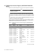
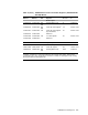

3.3.1 I/O Slot Configuration (IOSLOT) Register—1.C200.0000, 1.C200.0020
(Alternate address)
The I/O slot configuration register sets up the characteristics of each
TURBOchannel slot, whether built-in or option.
Each 3-bit register field corresponds to one slot and contains PBS bits. During
initialization, these bits are set to the default 0 for each slot. The meaning of
these bits is:
• P—Configuration bits for parity enable
When set to 1, a P bit specifies that the option corresponding to this slot
generates and checks parity on the TURBOchannel. This means that the
system checks parity on cycles during which the corresponding option is
driving the bus.
1
• B—Block-mode write
When set to 1, a B bit specifies that the option in this slot can perform
block-mode I/O write operations. This means that the hardware generates
a block-mode I/O write operation to the device, if a dense space I/O write
operation command from the CPU consists of contiguous longwords (as
described by the longword mask written from the CPU). If the longword mask
indicates several noncontiguous sets of longwords, the hardware reverts to
simple I/O writes.
• S—DMA scatter/gather mode
This bit is set at operating system boot time. When set to 1, a scatter/gather-
mode bit specifies that the scatter/gather map (virtual DMA) is enabled for
DMA transactions in the option corresponding to this slot. This bit cannot
be changed while a DMA operation to the corresponding slot is in progress.
While the bit can be different for each DMA transaction established by the
CPU, it should be changed only between DMA transactions.
The upper 5 bits of this register are the byte mask bits for I/O read operations.
To read less than a full I/O longword, write the register’s byte mask and set
the valid (V) bit. Once the masked I/O read operation through sparse space is
completed, clear the V bit.
Caution
Disable interrupts and exceptions before performing byte-masked I/O read
operations, since the IOSLOT register is a shared resource; re-enable
interrupts and exceptions after clearing the valid and byte mask bits in
the IOSLOT register.
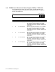
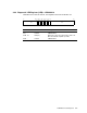
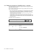
The register’s format and contents are:
06 05 03 02 0011 09 0815 14 1221 20 18 1727 26 24 2331 30
MR−0069−93RAGS
V MASK PBS8 PBS6 PBS5 PBS4 PBS3 PBS2 PBS1 PBS0PBS7
1
The system always generates parity when driving the bus, whether parity is enabled for
the slot or not.
3–10 TURBOchannel I/O Registers