
Instruction manual

2.5 CPU Registers
This section discusses:
• ABOX control register (Section 2.5.1)
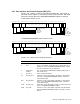
• The bus interface unit control register (Section 2.5.2)
Both registers must be assigned specific values at startup time, as shown in the
corresponding bit diagrams. Many values must be maintained during operation.
The required values of the registers whose contents affect system hardware are
outlined in this section.
1
PALcode initializes them during initial system startup,
unless otherwise noted.
2.5.1 ABOX Control Register (ABOX_CTL)
The ABOX is the address processing and external interface unit internal to the
DECchip 21064 CPU. The ABOX_CTL register contains bits that control ABOX
functions. The ABOX_CTL register is a 64-bit register of which only 6 bits are
used.
• During normal system operation of 300 models, bits in this register are set,
as shown in Figure 6.
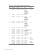
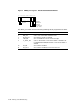
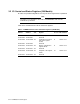
• During normal system operation of 400/500/600/700/800/900 models, bits in
this register are set as shown in Figure 7.
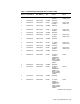
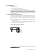
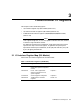
Figure 6 ABOX_CTL Register: 300 Models
07 06 05 04 03 02 01 0011 10 09 08
011010
WB_DIS
MCHK_EN
CRD_EN
IC_SBUF_EN
DC_EN
DC_FHIT
MR−0060−93RAGS
1
The DECchip 21064-AA Microprocessor Hardware Reference Manual contains a complete
list of registers.
Memory and I/O Addressing 2–9