
Instruction manual
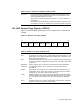
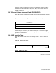

These four bytes are used by the firmware as an additional check on the NVR.
These data are initialized to 55
16
,AA
16
,33
16
,0F
16
, when an NVR failure is
detected at power on.
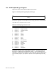
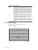
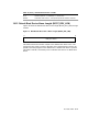
19.7 Ethernet Trigger Password Code (PASSWORD)
Figure 38 shows the NVR Ethernet trigger password code (PASSWORD) storage
location.
Figure 38 NVR Ethernet Trigger Password Code (PASSWORD)
MR−0162−93RAGS
PASSWORD<7:0>
0007
PASSWORD<15:8>
PASSWORD<23:16>
These three bytes are used by the console to verify that a request for trigger
boot from a remote node is valid. For security purposes, the password hashing
algorithm is not published.
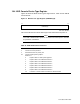
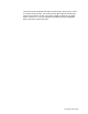
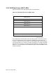
19.8 NVR Security Flags
Figure 39 shows the NVR security flags storage location. Table 71 shows the
fields.
Figure 39 NVR Security Flags
PSE PRV POWERUP_TIME<5:4> PSER
0007
MLO-012125
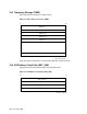
Table 71 NVR Security Flags
PSERR This 4-bit field counts password entry failures. The value of PSERR is
left unchanged by console initialization.
(continued on next page)
Nonvolatile RAM 19–7