
Instruction manual

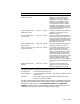
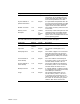

Component Address Length Description
Checksum MEMDSC 8 bytes A 64-bit 2’s complement sum (ignoring
overflows) of all the quadwords in the
memory data descriptor table, starting
at the second quadword in the table.
Physical address of
optional information
+ 8 8 bytes An implementation-dependent field. We
may store the physical address of a table
that contains all the bank configuration
register values in the DEC 3000 AXP.
Number of clusters + 10 8 bytes The number of memory clusters that are
in this table.
Memory cluster
descriptors
+ 18 number
of
clusters
38
16
The memory clusters descriptors for each
contiguous section of available memory.
There are at least two clusters in the
system, one for console/PALcode and one
for the operating system.
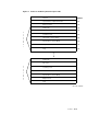
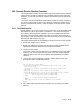
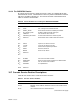
The next table lists the components of a memory cluster descriptor.
Component Address Length Description
Starting PFN Cluster_
address
8 bytes The PFN of the first page of a cluster.
Page count + 8 8 bytes The number of 8-KB pages in this
cluster.
Tested page count + 10 8 bytes The number of pages in the cluster that
have been found good. This gives the
operating system a high water mark, if
a complete test of memory has not been
done.
Virtual address of
cluster bitmap
+ 18 8 bytes The virtual address of the bitmap for
this memory cluster. If this cluster has
not been tested, the field is set to 0.
Physical address of
cluster bitmap
+ 20 8 bytes The physical address of the bitmap for
this memory cluster. If this cluster has
not been tested, this field is set to 0.
Bitmap checksum + 28 8 bytes If a bitmap address is supplied, a 64-bit
2’s complement sum (ignoring over flows)
of the bitmap is stored here.
Usage + 30 8 bytes This quadword determines who can
use this memory cluster. If bit <0> =
1, the cluster can be used only by the
console and the PALcode. If bit <0> = 0,
the cluster can be used only by system
software. Bits <63:1> must be zero.
16–52 Console