
Instruction manual


1.2 System Description: 400 Models
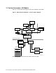
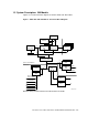
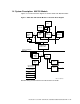
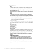
Figure 2 is a functional block diagram of the DEC 3000 AXP 400 models.
Figure 2 DEC 3000 AXP 400 Models: Functional Block Diagram
19
156
312
15
28
39
Memory
Data
ASICs (4)
ADDR
ASIC
CPU
CACHE
Scatter/
Gather Map
TURBOchannel
Interface ASIC
33
TC Option
Slots
TCDS
ASIC
IOCTL
ASIC
SCSI
SCSI
System Card Module
I/O Module
Non-Volatile
Time of Year
Serial Lines
Comm/Printer
ISDN
Audio In/Out
Ethernet
Boot ROM
MLO-012117
Numbers along communication lines indicate their bus width.
1–6 Introduction to the DEC 3000 Models 300/400/500/600/700/800/900 AXP