
Instruction manual
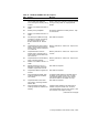
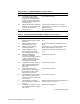
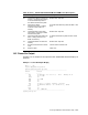
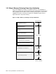
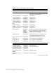
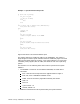

Table 47 (Cont.) 400/500/600/700/800/900 Model SROM Power-On Sequence
LED Activity Meaning
F5 Completed COREIO register test
and init. Initializing all memory
to zeroes followed by fetch of
SYS ROM manufacturing data.
Should never stop here.
F4 Fetched SYS ROM
manufacturing data. Loading
contents of SYS ROM into
memory.
SYS ROM manufacturing data was bad. Fatal
error.
F3 Completed load of SYS ROM
into memory. Fetching IO ROM
manufacturing data.
Should never stop here.
F2 Fetched IO ROM manufacturing
data. Loading contents of IO
ROM into memory.
IO ROM manufacturing data was bad. Fatal
error.
F1 Completed load of IO ROM into
memory.
Should never stop here.
F0 Execution transferred to console
code.
Cannot execute console code.
20 Machine check. Fatal error.
14.2 Power-On Output
Example 1 is an example of the output the DEC 3000 Model 500 AXP displays at
power on.
Example 1 Power-On Output Display
DEC 3000 - M500
Digital Equipment Corporation
System conducting power up tests
------------------------------------------------------------
Devnam Devstat
------- -------
CPU OK KN15-AA - V3.0-S0F0-I080 - sV2.1 - DECchip 21064
OSC OK 150 MHz
ASIC OK
MEM OK 144MB
NVR OK
CXT OK
SCC OK ptr(0) = Present keybd(2) = Present
NI OK Ethernet Address: 08-00-2B-2A-21-80 , THICK
SCSI OK
ISDN OK
TC4 OK - PMAGB-BA
------------------------------------------------------------
System power up OK.
Powerup Initialization and Firmware Entry 14–5