
Instruction manual

9.5.2.6 DMA for Communication Receive Port and Printer Port
Receive DMA writes a longword containing data in byte 1 of the location specified
by the receive pointer; the pointer is then incremented. When the DMA begins
filling the second half ofa4KBpage, an interrupt is generated to indicate that
the buffer is filling up. Software should disable DMA, allocate a new page buffer,
and update the pointer before restarting DMA.
If an error occurs and ends a DMA, error information is reported in the SIR.
Refer to Section 7.3.1 for information about SCC DMA pointer programming.
The keyboard and mouse ports must not be run at higher than 9600 baud, unless
the duty cycle is sufficiently slow (which is usually the case).
The communication port (SCC-0) implements TX, RX, DTR, DSR, RTS, CTS, CD,
SS, SI, TXC, RXC, and RI control signals and requires no extra signals to support
full modem control. The printer port implements TX, RX (and return), DTR, DSR,
and control signals. Loopback modes are not supported.
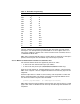
Table 34 lists SCC signal connections:
Table 34 SCC Signal Connections
Source Function Direction SCC-Signal
Mouse TxD Output SCC(0)-A TxD
Mouse RxD Input SCC(0)-A RxD
Com DTR Output SCC(0)-A ~DTR
Com RTS Output SCC(0)-A ~RTS
Com SI Input SCC(0)-A ~CTS
Com RI Input SCC(0)-A ~DCD
Com DSR Input SCC(0)-A ~SYNC
Com TxD Output SCC(0)-B TxD
Com RxD Input SCC(0)-B RxD
Com TRxCB Input SCC(0)-B TxC
Com RTxCB Input SCC(0)-B RxC
Com SS Output SCC(0)-B ~RTS
Com CTS Input SCC(0)-B ~CTS
Com CD Input SCC(0)-B ~DCD
Keyboard TxD Output SCC(1)-A TxD
Keyboard RxD Input SCC(1)-A RxD
Printer DTR Output SCC(1)-A ~DTR
Printer DSR Input SCC(1)-A ~SYNC
Printer TxD Output SCC(1)-B TxD
Printer RxD Input SCC(1)-B RxD
The SCC dual UART data register can be read and written directly. Other
register accesses require performing two steps.
1. The register address pointer (RAP) must be written with the address of the
register.
9–12 I/O Programming