
User Guide
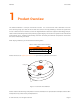
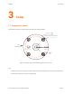
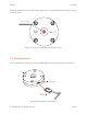

Table Of Contents
FSE1001 User Guide
3 Setup
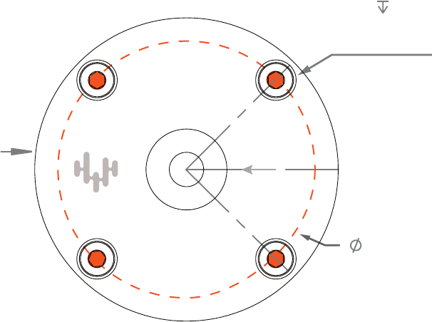
3.1 Mounting the sensor
The FSE1001 must be mounted using the through holes indicated below.
4 x M4x0.7
THROUGH HOLES
FOR SOCKET HEAD SCREWS
USB
CONNECTOR
50
FSE1001
APPLY
LOAD
HERE
45°
Figure 3.1: Bottom view of the FSE1001 (measurements in mm)
Tips:
• Mount the sensor as closely as possible to the area that will undergo the force you will be measuring.
• Make sure the base of the sensor is solidly fixed.
© 2017 Variense, Inc. All rights reserved. Page 3