V ARIENSE SENSE YOUR WORLD Uni-Axial Force Sensor FSE1001 User Guide Version 1.0 July 2017 © 2017 VARIENSE INC.
Contents 1 Product Overview 1 2 Safety 2 3 Setup 3.1 Mounting the sensor . . . . . . . . . . . . . . . . . . . . . . . . . . . . . . . . . . . . . . . . . . . 3.2 Wiring the sensor . . . . . . . . . . . . . . . . . . . . . . . . . . . . . . . . . . . . . . . . . . . . . 3 3 4 4 Software 4.1 FSE-1 Reader . . . . . . . . . . . . . . 4.1.1 Interface . . . . . . . . . . . . 4.1.2 Menu bar . . . . . . . . . . . 4.1.3 Graph and recording display 4.2 User integration . . . . . . . . . . . . 4.2.
List of Figures 1.1 Overview of the FSE1001 . . . . . . . . . . . . . . . . . . . . . . . . . . . . . . . . . . . . . . . . . 1 3.1 Bottom view of the FSE1001 (measurements in mm) . . . . . . . . . . . . . . . . . . . . . . . . . 3.2 Top view of the FSE1001 (measurements in mm) . . . . . . . . . . . . . . . . . . . . . . . . . . . 3.3 Wiring diagram of the FSE1001 . . . . . . . . . . . . . . . . . . . . . . . . . . . . . . . . . . . . . 3 4 4 4.1 4.2 4.3 4.4 4.5 4.6 Overview of the FSE-1 Reader . . .
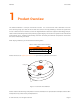
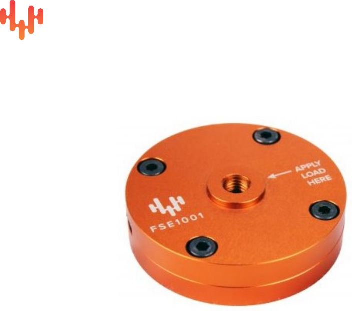
FSE1001 1 User Guide Product Overview The Variense FSE1001 is a unique uni-axial force sensor. It is a round sensor with a diameter of 60 mm and a sensing range up to 1000 N. All uni-axial force sensors work by exhibiting a variation of signal when a force is exerted on their surfaces; but the new digital FSE1001 is based on capacitive technology that provides enhanced sensitivity without compromising signal integrity. The result is low system noise and reduced measurement errors.
FSE1001 2 User Guide Safety Please read the following information before using the FSE1001. • Always respect the environmental conditions presented in the table below. The FSE1001 has not been tested for use in extreme environments. • Always handle the FSE1001 with care. It is made of metal and plastic and has sensitive electronic components inside, and can be damaged if dropped, burned, punctured or crushed. • Do not force a connector into a port.
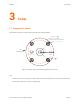
FSE1001 3 User Guide Setup 3.1 Mounting the sensor The FSE1001 must be mounted using the through holes indicated below. 4 x M4x0.7 THROUGH HOLES FOR SOCKET HEAD SCREWS 45° USB CONNECTOR FSE1001 APPLY LOAD HERE 50 Figure 3.1: Bottom view of the FSE1001 (measurements in mm) Tips: • Mount the sensor as closely as possible to the area that will undergo the force you will be measuring. • Make sure the base of the sensor is solidly fixed. © 2017 Variense, Inc. All rights reserved.
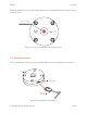
FSE1001 User Guide Attach the FSE1001 to the force measurement point using the identified threaded hole situated on the top side of the sensor. 7 M8x1.25 THREADED HOLE APPLY LOAD HERE FSE1001 Figure 3.2: Top view of the FSE1001 (measurements in mm) 3.2 Wiring the sensor Use the included cable, or any Type A to Micro-B USB cable, to connect your FSE1001 to your computer. Sensor Micro USB Type B Female Micro USB Type B Connector Figure 3.3: Wiring diagram of the FSE1001 © 2017 Variense, Inc.
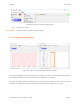
FSE1001 User Guide 4 Software 4.1 FSE-1 Reader You can buy our software (FSE-1 Reader) directly from our website. 4.1.1 Interface 1 2 3 4 5 6 Figure 4.1: Overview of the FSE-1 Reader 1- Menu bar 2- Tool bar 3- Connection status 4- Current forces display 5- Graph and recording display 6- Status bar © 2017 Variense, Inc. All rights reserved.
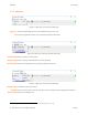
FSE1001 User Guide 4.1.2 Menu bar Figure 4.2: Menu bar of the FSE-1 Reader (File) Export as... Export recorded data as one of the available formats (.txt or .csv). Exit Close the application (warning: any unsaved recordings will be lost). Figure 4.3: Menu bar of the FSE-1 Reader (Recorder) Start Recording Begin recording incoming data. Stop Recording Stop recording. Recorded data can now be exported. Clear Recording Delete all recorded data. Any unsaved recordings will be lost. Figure 4.
FSE1001 User Guide Figure 4.5: Menu bar of the FSE-1 Reader (Help) Help... Open the User Guide. About FSE1001... Display information about the connected sensor. 4.1.3 Graph and recording display Figure 4.6: Graph and recording display of the FSE-1 Reader The "Graph" tab displays the past few seconds of force data, even when it is not recording. While recording, the background changes color and the elapsed time is displayed in the status bar. The "Data" tab displays only the recorded data.
FSE1001 User Guide 4.2 User integration If you are not using our user interface, please note that the FSE1001 will continuously stream data through the USB cable as soon as the cable is plugged in. However, no data is saved within the sensor itself. 4.2.1 Connection The FSE1001 is seen as a serial device (COM port) when plugged into a computer. Since the sensor uses a USB CDC to emulate serial communication through USB protocol, no settings need to be specified when opening the serial port. 4.2.
FSE1001 User Guide 4.2.3 Messages format The sensor uses the following format when sending calculated forces: Table 4.
FSE1001 5 User Guide Specifications 5.1 Mechanical dimensions 60 APPLY LOAD HERE FSE1001 16 LOADING AREA 16 Units: mm Figure 5.1: Dimensions of the Variense FSE1001 5.2 Technical specifications Table 5.1: Technical specifications of the FSE1001 Feature Condition Value Unit Outer 60 mm 15 mm Note Mechanical specifications Diameter Thickness Weight Overload capacity 80 g Fz 200 % +/- Fz up to 1000 N < 1.2 %FS <1 %FS 2.8 - 5.
FSE1001 6 User Guide Warranty Variense warrants the FSE1001 against defects in material and workmanship for a period of one year from the date of receipt when used as instructed. During the warranty period, Variense will repair or replace any defective product free of charge. If the equipment is sent to us during the warranty period and found to meet all published specifications, Variense will charge standard verification fees.
FSE1001 7 User Guide Contact Web www.variense.com Email support@variense.com Phone +1 (844) 827-4367 © 2017 Variense, Inc. All rights reserved.