
User Guide


VMU931 User Guide
3 Setup
3.1 Mounting the sensor
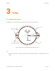
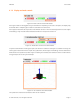
The VMU931 must be mounted using the holes located on each side of the sensor.
M2.5x0.45
2
THROUGH HOLE
X
Y
Z
VMU931
DOWEL PINS
MOUNTING HOLES
1
R18
R17
12°
Figure 3.1: Top view of the VMU931 (measurements in mm)
Tips:
• Make sure the sensor is solidly fixed to prevent any unwanted movement or vibration during normal
usage.
© 2017 Variense, Inc. All rights reserved. Page 3