V ARIENSE SENSE YOUR WORLD Inertial Measurement Unit VMU931 User Guide Version 1.0 July 2017 © 2017 VARIENSE INC.
Contents 1 Product Overview 1 2 Safety 2 3 Setup 3.1 Mounting the sensor . . . . . . . . . . . . . . . . . . . . . . . . . . . . . . . . . . . . . . . . . . . 3.2 Wiring the sensor . . . . . . . . . . . . . . . . . . . . . . . . . . . . . . . . . . . . . . . . . . . . . 3 3 4 4 Software 4.1 VMU Reader . . . . . . . . . . . . 4.1.1 Interface . . . . . . . . . . 4.1.2 Menu bar . . . . . . . . . 4.1.3 Display and main controls 4.2 User integration . . . . . . . . . . 4.2.1 Connection . . . . . . . . 4.2.
List of Figures 1.1 Overview of the VMU931 . . . . . . . . . . . . . . . . . . . . . . . . . . . . . . . . . . . . . . . . . 1 3.1 Top view of the VMU931 (measurements in mm) . . . . . . . . . . . . . . . . . . . . . . . . . . . 3.2 Wiring diagram of the VMU931 . . . . . . . . . . . . . . . . . . . . . . . . . . . . . . . . . . . . . 3 4 4.1 4.2 4.3 4.4 4.5 4.6 4.7 Overview of the VMU Reader . . . . . . Menu bar of the VMU Reader (View) . . Menu bar of the VMU Reader (Tools) . .
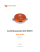
VMU931 1 User Guide Product Overview The new rugged VMU931 is a round IMU with a diameter of 31 mm, that fits 3-axis accelerometers, 3-axis gyroscopes and 3-axis magnetometers in a robust alumunium housing as shield against extreme environmental conditions. It is based on the latest MEMS technology, which is highly adaptive to various applications. Realtime data logging, maximum sensitivity and automatic factory calibration ensure that the sensor will fit your system proprely.
VMU931 2 User Guide Safety Please read the following information before using the VMU931. • Always respect the environmental conditions presented in the table below. The VMU931 has not been tested for use in extreme environments. • Always handle the VMU931 with care. It is made of metal and plastic and has sensitive electronic components inside, and can be damaged if dropped, burned, punctured or crushed. • Do not force a connector into a port.
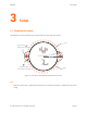
VMU931 User Guide 3 Setup 3.1 Mounting the sensor The VMU931 must be mounted using the holes located on each side of the sensor. R17 M2.5x0.45 2 THROUGH HOLE VMU931 12° Y 1 DOWEL PINS MOUNTING HOLES Z X R18 Figure 3.1: Top view of the VMU931 (measurements in mm) Tips: • Make sure the sensor is solidly fixed to prevent any unwanted movement or vibration during normal usage. © 2017 Variense, Inc. All rights reserved.
VMU931 User Guide 3.2 Wiring the sensor Use the included cable, or any Type A to Micro-B USB cable, to connect your VMU931 to your computer. Sensor VM U9 31 Y X Z Micro USB Type B Female Micro USB Type B Connector Figure 3.2: Wiring diagram of the VMU931 © 2017 Variense, Inc. All rights reserved.
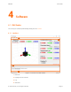
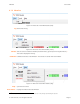
VMU931 User Guide 4 Software 4.1 VMU Reader You can buy our software (VMU Reader) directly from our website. 4.1.1 Interface 1 2 3 4 Figure 4.1: Overview of the VMU Reader 1- Menu bar 2- Display and main controls 3- Log 4- Status bar © 2017 Variense, Inc. All rights reserved.
VMU931 User Guide 4.1.2 Menu bar Figure 4.2: Menu bar of the VMU Reader (View) Log Show/Hide the log. Figure 4.3: Menu bar of the VMU Reader (Tools) Self-test Test the sensors inside the VMU931 (accelerometers, gyroscopes and magnetometers).1 The result is displayed in the log. Calibration Calibrate the biases of the VMU931.1 The biases are saved within the VMU931. Figure 4.4: Menu bar of the VMU Reader (Help) Help... Open the User Guide. About VMU931... Display information about the VMU931.
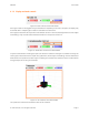
VMU931 User Guide 4.1.3 Display and main controls Figure 4.5: Main controls of the VMU Reader Each type of data can be toggled using the checkboxes. Depending on the user’s computer, the display may be slowed down if multiple types of data are activated at the same time. Some types of data limit the output rate of the VMU931 to 200 Hz when activated (quaternions, Euler angles and heading). They must all be deactivated to benefit of an output rate of 1000 Hz. Figure 4.
VMU931 User Guide 4.2 User integration If you are not using our user interface, please note that the VMU931 will continuously stream data through the USB cable as soon as the cable is plugged in. However, no data is saved within the sensor itself. 4.2.1 Connection The VMU931 is seen as a serial device (COM port) when plugged into a computer. Since the sensor uses a USB CDC to emulate serial communication through USB protocol, no settings need to be specified when opening the serial port. 4.2.
VMU931 User Guide If none of the quaternions, Euler angles or heading is active, the resolution of the accelerometers and the gyroscopes can be changed using the following commands: Table 4.
VMU931 User Guide 4.2.3 Messages format There are 2 types of messages the sensor can send: • Text string • Data In the case of a string of text, the message will have the following structure: Table 4.
VMU931 User Guide As for the message itself, the structure goes as follow depending on the type of the data: Table 4.
VMU931 User Guide The value of each status is determined according to the following tables: Table 4.8: Status message - Sensors status 7 6 5 4 3 2 1 0 — — — — — MAG GYRO ACC 0 = OFF 1 = ON Table 4.9: Status message - Sensors resolution 7 6 5 4 3 2 1 0 2000 dps 1000 dps 500 dps 250 dps 16 G 8G 4G 2G Gyroscopes Accelerometers 0 = NOT SELECTED 1 = SELECTED Table 4.
VMU931 5 User Guide Specifications 5.1 Mechanical dimensions 31 7.5 VMU931 Y Z 2 X 41 Units: mm Figure 5.1: Dimensions of the VMU931 © 2017 Variense, Inc. All rights reserved.
VMU931 User Guide 5.2 Technical specifications Table 5.1: Technical specifications of the VMU931 Feature Condition Value Unit Outer 31 mm 9.5 mm 15 g Note Mechanical Specifications Diameter Thickness Weight Environmental Protection Shock Tolerance aluminum case IP64 10,000 g Pitch / Roll < 0.2 ° Heading < 0.5 ° <5 °/hr Selectable up to 1,000 Hz DC 2.8 - 5.
VMU931 6 User Guide Warranty Variense warrants the VMU931 against defects in material and workmanship for a period of one year from the date of receipt when used as instructed. During the warranty period, Variense will repair or replace any defective product free of charge. If the equipment is sent to us during the warranty period and found to meet all published specifications, Variense will charge standard verification fees.
VMU931 7 User Guide Contact Web www.variense.com Email support@variense.com Phone +1 (844) 827-4367 © 2017 Variense, Inc. All rights reserved.