
User guide


LA Stand-Alone Product User Guide
Revision A7
Page 16
2.4.7 Signal Connector Electrical Interface
The following drawings illustrate the electrical interface for the J8 & J9 signal connectors. Note that there
are 2 configurations available from the factory, one with optical isolation and one without. Please be sure
to use the correct drawing. Also note that J8 can be either DB15M (male) or DB15F (female).
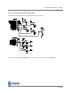
2.4.7.1 J8 & J9 Electrical Interface, Optically Isolated
For the optically isolated version of J8, Opto Common is pin 14 and can be any voltage in the range 5-
24vdc. Active signal inputs are low referenced to the supply providing the Opto Common voltage.
Alternatively a common ground can be provided on pin 14 and 5-24vdc can be used to activate the
individual inputs. Note that the Fault output is open collector with no internal current limiting
resistor. The user must provide an external current limiting resistor to limit current to no more
than 200mA.
Note: Pin outs are shown for DB15M connector option. Refer to 2.4.8 or 2.4.9 as appropriate.