2+1 SATA 6G & PATA PCI-E COMBO HOST CARD WITH RAID User Manual Model: UGT-IS602R All brand names and trademarks are properties of their respective owners. www.vantecusa.
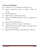
Features and Benefits z PCI-Express 2.0 x 1 (Compatible with PCI-Express 1.0) z Supports communication speeds of 6.0Gbps, 3.0Gbps, and 1.5Gbps z Hot plug and Hot Swap z Support Native Command Queuing (NCQ) z Supports Port Multiplier FIS based switching or command based switching z Support ATA and ATAPI commands z Compatible with SATA 6G, 3G and 1.
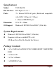
Specifications Model: UGT-IS602R Bus interface: PCI-Express 2.0 x 1 Ports: 2 x Internal SATA 6G ports (Backward compatible with SATA 3.0Gbps & 1.
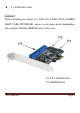
z 2 x SATA Data Cable Layout Before Installing the Vantec 2+1 SATA 6G & PATA PCI-E COMBO HOST CARD WITH RAID, please see the photo below highlighting the available SATA6G, IDE/PATA ports of the card.
Hardware Installation 1. Turn off the power to your computer. 2. Unplug the power cord and remove your computer’s cover. 3. Remove the slot bracket from an available PCIe slot. 4. To install the board, carefully align the card’s bus connector with the selected PCIe slot on the motherboard. Push the board down firmly. 5. Attach your internal devices to the 2+1 SATA 6G & PATA PCI-E COMBO HOST CARD WITH RAID. 6. Replace the slot bracket’s holding screw to secure the card. 7.
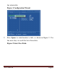
the virtual disk. Figure 1 Configuration Wizard 2. Press Space to select/unselect a disk, as shown in Figure 2. Use the arrow keys to scroll the list of free disks.
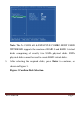
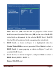
Note: The 2+1 SATA 6G & PATA PCI-E COMBO HOST CARD WITH RAID supports the creation of RAID 0 and RAID 1 virtual disks comprising of exactly two SATA physical disks. PATA physical disks cannot be used to create RAID virtual disks. 3. After selecting the required disks, press Enter to continue, as shown in Figure 3.
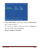
4. Create Virtual Disk by configuring its setting in the Information pane, as shown in Figure 4. The controls for making selection are listed in the Help pane when an available setting is highlighted.
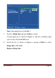
Note: Max size (MB) and Disk ID are properties of the virtual disk that cannot be edited. Max size (MB) in the size of the RAID virtual disk as determined by the selected RAID Level. Disk ID lists the IDs of the physical disks comprising the virtual disk. 5. RAID Level, as shown in Figure 4, is highlighted when the Create Virtual Disk screen is presented. Press Enter to select a RAID Level. A menu pops-up, as shown in Figure 5, and lists available RAID levels. 6.
Note: The default Level is RAID 0. 7. Scroll to Stripe Size and press Enter to select. A menu pops-up, as shown in Figure 6, and lists available stripe sizes for the selected RAID level. 8.
Note: The default size is 64 KB. 9. Scroll to Gigabyte Rounding and press Enter to select. A menu pops-up, as shown in Figure 7, and lists available stripe sizes for the selected RAID level. 10.
Note: The default setting for Gigabyte Rounding is 1G. 11. Scroll to Quick Init and press Enter to enable to disable quick initialization of the virtual disk. A menu pops-up, as shown in Figure 8, and lists available options for quick initialization of the virtual disk. 12. Scroll the list, as shown in Figure 8, and press Enter to select Quick Init (Yes, No).
Note: The default setting for Quick Init is Yes. 13. Scroll to VD Name and the Default name is cleared for a new name, as shown in Figure 9. Type a new name and press Enter to confirm the selection.
. After configuring the virtual disk, scroll to Next, as shown in Figure 10. Press Enter to create the virtual disk.
. Please Y to select Yes, as shown in Figure 11, to confirm the creation of the virtual disk. The virtual disk is now listed in the Topology pane, as shown in Figure 12.
Figure 12 Virtual Disk in Topology Pane UGT‐IS602R Page 16
Managing Virtual Disks This section contains the following topics: z Viewing Properties of Virtual Disk z Erasing RAID Configuration Data z Rebuilding Virtual Disk z Deleting Virtual Disk Viewing Properties of Virtual Disk To view the properties of a virtual disk, scroll to the Virtual Disk (VD 0: Default in Figure 13) in the Topology pane. The properties of the virtual disk are displayed in the Information pane when VD 0: Default is highlighted, as shown in Figure 13.
Erasing RAID Configuration Data Note: The RAID controller stores RAID configuration data on all physical disks that are part of a virtual disk. RAID configuration data must be erased on the physical disk before it can be used with another virtual disk. 1. In the Topology pane, select Physical Disk (VD 0: Default > PD 0: ST3750330MS in Figure 14) and press Enter. A menu pops-up, as shown Figure 14. 2. Select Delete to delete the virtual disk, as shown in Figure 14. 3.
Figure 14 Erase RAID Configuration Data Rebuilding Virtual Disk Note: The 2+1 SATA 6G & PATA PCI-E COMBO HOST CARD WITH RAID BIOS supports manual rebuilding of RAID 1 virtual disks. The rebuild process is both initiated and complete in the BIOS. The Marvell RAID Utility (MRU), which runs in an OS environment, cannot be used to either initiate, resume, or complete the rebuild process. Spare physical disks are not supported. To manually rebuild a RAID 1 virtual disk 1.
changed from Functional to Degrade, as shown in Figure 15. Figure 15 Virtual Disk Properties: Degrade VD 2. Replace the faulty physical disk with an identical physical disk. Note: If an identical disk is unavailable, use a replacement physical disk or larger size or one with a slightly smaller size as determined the Gigabyte Rounding setting for the virtual disk.
3. In the Topology pane, scroll to Virtual Disks (VD 0: New_VD in Figure 17), and press Enter to select. A menu pops-up, as shown in Figure 17 Scroll to Rebuild and press Enter to configure the rebuild process.
4. Scroll through the list of free disk, as shown Figure 18, and press Space to select or unselect a replacement physical disk. Press Enter to continue.
5. Press Y to select Yes, as shown in Figure 19, when prompted to confirm the rebuild process.
6. The status of the Rebuild process is reflected in the properties of the virtual disk, as shown in Figure 20. Figure 20 Rebuild Status To pause the rebuild process 1. In the Topology pane, scroll to the partially rebuild Virtual Disk. 2. Press Enter to view available operation on Virtual Disk. 3. Scroll to Pause and press Enter to pause the rebuild process. Note: Incomplete rebuild procedures are paused upon exiting the BIOS.
To pause the rebuild process 1. In the Topology pane, scroll to the partially rebuild Virtual Disk. 2. Press Enter to view available operation on Virtual Disk. 3. Scroll to Resume and press Enter to resume the rebuild process. Note: The rebuild process is both initiated and completed in the BIOS. The Marvell RAID Utility (MRU), which runs in an OS environment, cannot be used to either initiate, pause, resume, or complete the rebuild process. Deleting Virtual Disk To delete a virtual disk 1.
Driver Installation Note: Driver can also be found and downloaded from our website at www.vantecusa.com For Windows® XP/Server 2003 For A New Installation A new installation requires a floppy disk for the driver installation.
below. 1. Follow Microsoft’s Windows installation procedure. 2. At the Windows Setup screen, press F6 to install the driver. 3. When prompted, press S to specify the location of the driver. 4. Insert the floppy disk, then press Enter. 5. Scroll to Marvell shared library (install first) using the arrow keys and press Enter to select. 6. Press S again to select the second device. 7. Scroll to Marvell 91xx SATA Controller 32bit Driver and press Enter to select. 8.
OK. (Change D:\ to match your CD-ROM drive letter) 14. Follow the on-screen instructions to complete the installation. 15. After successful installation, the device is listed in the Device Manager as Marvell 91xx Config Device (under System Device) For An Existing Installation 1. Please insert the CD driver bound with 2+1 SATA 6G & PATA PCI-E COMBO HOST CARD WITH RAID into your CD-ROM Drive. 2. At the Windows desktop, click Start, then Run. 3. Type D:\UGT-IS602R\XP_2003_Vista_2008_7\Setup.
below. 1. Follow Microsoft’s Windows installation procedure. 2. At the Windows Setup screen, press F6 to install the driver. 3. When prompted, press S to specify the location of the driver. 4. Insert the floppy disk, then press Enter. 5. Scroll to Marvell shared library (install first) using the arrow keys and press Enter to select. 6. Press S again to select the second device. 7. Scroll to Marvell 91xx SATA Controller 64bit Driver and press Enter to select. 8.
OK. (Change D:\ to match your CD-ROM drive letter) 14. Follow the on-screen instructions to complete the installation. 15. After successful installation, the device is listed in the Device Manager as Marvell 91xx Config Device (under System Device) For An Existing Installation 1. Please insert the CD driver bound with 2+1 SATA 6G & PATA PCI-E COMBO HOST CARD WITH RAID into your CD-ROM Drive. 2. At the Windows desktop, click Start, then Run. 3. Type D:\UGT-IS602R\XP_2003_Vista_2008_7\Setup.
3. Insert the CD driver bound with 2+1 SATA 6G & PATA PCI-E COMBO HOST CARD WITH RAID into your CD-ROM Drive, please select Marvell 91xx SATA 6G Controller (D:\UGT-IS602R\XP_2003_Vista_2008_7\Floppy32\mv91xx.inf), then press Next. (Change D:\ to match your CD-ROM drive letter) 4. Continue with Windows OS installation. 5. And there is an additional device Marvell 91xx Config SCSI Processor Device is detected when Windows starts for the first time. 6.
For An Existing Installation 1. Please insert the CD driver bound with 2+1 SATA 6G & PATA PCI-E COMBO HOST CARD WITH RAID into your CD-ROM Drive. 2. At the Windows desktop, click Start, then Run. 3. Type D:\UGT-IS602R\XP_2003_Vista_2008_7\Setup.exe, click OK. (Change D:\ to match your CD-ROM drive letter) 4. Follow the on-screen instructions to complete the installation. 5. Restart Windows to complete the installation. For Windows® Vista-x64/2008-x64/7-x64 For A New Installation 1.
letter) 4. Continue with Windows OS installation. 5. And there is an additional device Marvell 91xx Config SCSI Processor Device is detected when Windows starts for the first time. 6. Please insert the CD driver bound with 2+1 SATA 6G & PATA PCI-E COMBO HOST CARD WITH RAID into your CD-ROM Drive. 7. At the Windows desktop, click Start, then Run. 8. Type D:\UGT-IS602R\XP_2003_Vista_2008_7\Setup.exe, click OK. (Change D:\ to match your CD-ROM drive letter) 9.
3. Type D:\UGT-IS602R\XP_2003_Vista_2008_7\Setup.exe, click OK. (Change D:\ to match your CD-ROM drive letter) 4. Follow the on-screen instructions to complete the installation. 5. Restart Windows to complete the installation. To Verify Driver Installation 1. Right click My Computer and click Manage. 2. Select Device Manager. 3.
UGT‐IS602R Page 35
Warranty The 2+1 SATA 6G & PATA PCI-E COMBO HOST CARD WITH RAID comes with a 1 year limited warranty(90 day parts). If your unit becomes defective within that time frame, please go to www.vantecusa.com for information on how to receive warranty exchange or repair. Cosmetic defects and missing parts are not covered under this warranty. Please check the contents of the unit to make sure you received all parts. Also, check for any cosmetic flaws.