6-Port SATA II 150 PCI Host Card w/RAID User Manual Model: UGT-ST310R All brand names and trademarks are properties of their respective owners. www.vantecusa.
Table of Contents 1. Bus Interface.......................................... 3 2. Connectors............................................. 3 3. Package Contents.................................. 3 4. System Requirements............................ 4 5. Hardware Description............................. 4 6. Hardware Installation ............................. 5 7. Device Connection ................................. 5 8. RAID Arrays ........................................... 6 RAID 0 (Striping)................
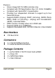
Features • • • • • • • • Silicon Image SiI3114 SATA controller chip Compliant with PCI Specification, Rev. 2.3, 32-bit, 33/66Mhz Compliant with Serial ATA 1.
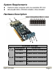
System Requirements z z Pentium-class computer with one available PCI slot Windows® 2000, XP/2003 32/64bit, Vista 32/64bit Hardware Description JP J1-J4 J5-J8 UGT-ST310R G (Jumper Settings) Description Active Port 1-2 close Enable SATA Connector F 2-3 close Enable SATA Connector C 1-2 close Enable SATA Connector E 2-3 close Enable SATA Connector D Page 4
Note: There are six SATA ports in 6-Port SATA II 150 PCI Host Card w/RAID. We name these ports from A through F. Ports A to D are internal SATA ports. Ports E and F are external SATA ports. Changing the jumper settings allows you to select between external and internal ports to use. By default, Port A, B, C and D are working. Hardware Installation 1. 2. 3. 4. 5. 6. Turn Off the power to your computer and any other connected peripheral devices. Unplug the power cord form the back of the computer.
4. 5. 6. drive. Attach the other end of the Serial ATA cable to the Serial ATA controller on the 6-Port SATA II 150 PCI Host Card w/RAID. Follow the same instructions to connect up to four hard drives. Device connection is now complete. Replace the computer cover and reconnect the power cord. RAID Arrays RAID Arrays are setup in the 6-Port SATA II 150 PCI Host Card w/RAID’s BIOS. RAID 0 (Striping) This RAID array to be used on New/Blank hard drives. Striping will destroy existing data on the hard drive.
Select RAID0, then press Enter. Select the number of drives then press Enter. Select Auto configuration, then press Enter. Input the RAID size, press Enter. When asked Are You Sure (Y/N)?, press Y to accept. Press Ctrl+E to exit the BIOS. When asked Are you sure to exit (Y/N)?, press Y to exit and reboot. 10. Continue with FDISK and FORMAT steps as if you were installing a conventional hard drive. 3. 4. 5. 6. 7. 8. 9. Manual configuration 1. 2. 3. 4. 5. 6. 7. 8. 9. 10. 11. 12. 13. 14.
RAID 1 (Mirror) For New/Blank Hard Drives 1. 2. 3. 4. 5. 6. 7. 8. 9. As the BIOS boots press Ctrl+S or F4 when prompted to enter the RAID BIOS. At the next screen select Create RAID Set, then press Enter. At the next screen select RAID1 then press Enter. Select Auto configuration, then press Enter. Input the RAID size, press Enter. When asked Are You Sure(Y/N)?, press Y to accept. Press Ctrl+E to exit the BIOS. When asked Are you sure to exit(Y/N)?, press Y to exit and reboot.
. Input the RAID size, press Enter. 10. Press Ctrl+E to exit the BIOS. 11. When asked Are you sure to exit(Y/N)?, press Y to exit and reboot. Note: If during boot the RAID BIOS reports an RAID1 set is in Rebuild status, The rebuild will continue after boot sequence is complete, disregard the message, continue booting, and let the Mirror rebuild.
use existing hard drive(s) with data. To create a RAID 0+1 set four hard drives are required. Auto configuration (recommended) The default chunk size is 64k when selecting Auto configuration. 1. As the BIOS boots press Ctrl+S or F4 when prompted to enter the RAID BIOS. 2. At the next screen select Create RAID Set, then press Enter. 3. Select RAID10, then press Enter. 4. Select Auto configuration, then press Enter. 5. Input the RAID size, press Enter. 6.
6. 7. 8. 9. 10. 11. 12. 13. 14. 15. 16. Select chunk size from 8k, 16k, 32k, 64 or 128k, then press Enter. Select the first drive, press Enter. Select the second drive, press Enter. Select the third drive, press Enter. Select the fourth drive, press Enter. Select Create without data copy then press Enter. Input the RAID size, press Enter. When asked Are You Sure(Y/N)?, press Y to accept. Press Ctrl+E to exit the BIOS. When asked Are you sure to exit(Y/N)?, press Y to exit and reboot.
Enter. Select RAID5, then press Enter. Select the number of drives then press Enter. Select Auto configuration, then press Enter. Input the RAID size, press Enter. When asked Are You Sure(Y/N)?, press Y to accept. Press Ctrl+E to exit the BIOS. When asked Are you sure to exit(Y/N)?, press Y to exit and reboot 10. Continue with FDISK and FORMAT steps as if you were installing a conventional hard drive. 3. 4. 5. 6. 7. 8. 9. Manual configuration 1. 2. 3. 4. 5. 6. 7. 8. 9. 10. 11. 12. 13. 14.
and reboot. 15. Continue with FDISK and FORMAT steps as if you were installing a conventional hard drive. CONCATENATION (JBOD) This RAID array allows you to use one, two, three or four hard drives to a array. It does not provide any data protection or performance improvement but can be useful for utilizing leftover space on disks. 1. As the BIOS boots press Ctrl+F4 or F4 when prompted to enter the RAID BIOS. 2. At the next screen select Create RAID Set, then press Enter. 3.
2. 3. 4. Select Delete RAID Set, then press Enter. Select the RAID set then press Enter. When asked Are You Sure(Y/N)?, press Y to confirm. Resolving Conflicts When a RAID set is created, then metadata written to the disk includes drive connection information. If, after a disk failure, the replacement disk was previously part of a RAID set (or used in another system), it may have conflicting metadata.
BIOS Configuration The 6-Port SATA II 150 PCI Host Card w/RAID BIOS will appear every time your system starts up. If the BIOS doesn’t show, please try your controller in another PCI slot. During this (POST) process, the BIOS will show up and indicate the devices attached to it. Driver Installation For Windows® 2000 For A New Installation A new installation requires a floppy disk for the driver installation.
2. 3. 4. 5. 6. 7. 8. to Windows. At Found New Hardware Wizard, click Next. Select Search for a suitable driver for my device (recommend) then click Next. Insert the driver CD, check CD-ROM drives, uncheck the other boxes, click Next, then click Next again. If the Digital Signature Not Found message appears, click Yes. Our driver has been thoroughly tested for stability and compatibility. Click Finish. Repeat steps 2-6. Restart Windows to complete the driver installation.
For An Existing Installation 1. Setup the RAID Array prior to driver installation and boot up to Windows. 2. At the Found New Hardware Wizard, select No, not this time, then click Next. 3. Insert the driver CD, select Install the software automatically (Recommended), and click Next. 4. Click Finish. 5. Restart Windows to complete the driver installation. For Windows® XP-x64/Server 2003-x64 For A New Installation A new installation requires a floppy disk for the driver installation.
1. 2. 3. 4. 5. Setup the RAID Array prior to driver installation and boot up to Windows. At the Found New Hardware Wizard, select No, not this time, then click Next. Insert the driver CD, select Install the software automatically (Recommended), and click Next. Click Finish. Restart Windows to complete the driver installation. For Windows® Vista For A New Installation A new installation requires a floppy disk for the driver installation.
3. 4. Please insert driver CD, click Next. Click Close to complete the installation. For Windows® Vista-x64 For A New Installation A new installation requires a floppy disk for the driver installation. To make this floppy disk, copy the contents of the “UGT-ST310R\XP_2003_Vista\64bit” folder, found on the driver CD, onto a blank floppy disk then follow the directions below. 1. 2. 3. 4. 5. Setup the RAID Array prior to Windows installation. Follow Microsoft’s Windows installation procedure.
2. 3. Select Device Manager. Double click SCSI and RAID Controller (Storage controllers), then double click Silicon Image SiI 3114 SoftRAID 5 Controller to display driver properties. A message this device is working properly is displayed in the dialog box, the driver has been correctly installed. SATA RAID 5 Management Software Installation For Windows® 2000/XP/Server 2003/Vista 1. 2. 3. 4. Please insert the driver CD into your CD-ROM Drive. At the Windows desktop click Start, then Run.