
Installation manual


RE Owners Manual
5-2
Copyright
2001 Phone: (614) 771-271 RE-4500
Vanner Inc. FAX: 614-771-4904 Installation Manual
4282 Reynolds Dr. www.vanner.com Rev 10d
Hilliard Ohio 43026 RE Owners_Manual_Rev10d D99988
INCORPORATED
INCORPORATEDINCORPORATED
INCORPORATED
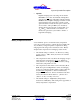
ESC
MENU
ALARM
SETTINGS ALARMS
ADVANCED HELP
INVERTER/CHARGER
CONTROL
RE-4500
Large Inverter/
Charger
Small
Inverter/
Charger
Transfer
Relays
Controller
Display
On/Off Switch
LEDs, Relays
Relay A,B,C,D
To AC Load
240 VAC
(or ACM)
To/From Grid
240 VAC
(or ACM)
To/From
DC Source
(or DCM)
+VDC
Voltage
GND
PC running RE-ICC for Windows
OR
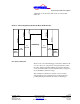
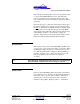
The components that make up the RE are:
•
System Controller Board
The System Controller is the brain of the system that
monitors and controls the operations of the system. It
receives commands from the user entered on the RE-ICC,
and executes those commands to control the system. It
controls all system operations: Inverting, Charging, Grid-
Tie, and Generator Control.
•
Large Inverter/Charger
The Large Inverter/Charger is responsible for converting
the DC Voltage from the batteries and the photo-voltaic
modules to split phase, 240 VAC. When in “Charger”
mode, if the batteries are low, this component will convert
the 240VAC from the Grid to the DC Voltage (either
24VDC or 48VDC, depending on the system) to charge the
batteries if they are low. The Large Inverter/Charger is
used by the system if the power required by the load is in
the range of 75 to 4500 watts.
Figure 5-1: Block Diagram