
Installation manual


Component Identification
4-9
Copyright
2001 Phone: (614) 771-271 RE-4500
Vanner Inc. FAX: 614-771-4904 Installation Manual
4282 Reynolds Dr. www.vanner.com Rev 10d
Hilliard Ohio 43026 RE Owners_Manual_Rev10d D99988
INCORPORATED
INCORPORATEDINCORPORATED
INCORPORATED
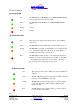
(22) Positive Termination From DC Power Source
Attach either +24 VDC or 48 VDC (depending on your model)
Positive feed to this terminal
Warning
Check Polarity Carefully! Attaching the Negative supply to this
terminal can result in loss of life, damage to the system, the
batteries, and voiding of Warranty.
Check your terminations carefully!
!!Make Certain that the proper voltage is connected to the unit –
24VDC for the RE24-4500, and 48VDC for the RE48-4500. Damage
will result if improper voltage is applied.
(23) Negative Termination From DC Power Source
Attach either +24 VDC or 48 VDC (depending on your model)
Negative (Ground) feed to this terminal.
Warning
This terminal is grounded to the inverter Chassis
Check Polarity Carefully! Attaching the Positive supply to this
terminal can result in loss of life, damage to the system, the
batteries, and voiding of Warranty.
Check your terminations carefully!
(24) Serial Control Connector
This RJ-11 jack is for serial communication between the RE-
4500 and the remote display (Inverter / Charger Controller) –
Vanner Part RE-ICC or RS-232 Control/Programming Cable.
Alternately this connector can be used to communicate with a
computer using RE-ICC For Windows using the Vanner
provided communications cable which comes with ICC for
Windows.
Warning
This connector is for the RE-ICC Remote Display or the Vanner
Serial Communications cable! Attaching any other device to this
connector can result in loss of life, damage to the system, and
voiding of the manufacturers Warranty.
Check your terminations carefully!