
Specifications


Owners Manual
SILENT RUNNER INVERTER/CHARGER POWER SYSTEM
18
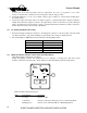
10. Plug AC output test light (eg. 100 watt trouble light) into 15A convenience receptacle and turn on to verify
inverter produces AC power and the Load Demand function powers up from stand-by mode. Applying any
AC load greater than 5 Watts should start inverter from Load Demand “stand by” mode.
11. Connect and activate AC shore/power (or generator).
12. When shore/utility power (or generator) has been connected the inverter the following should occur:
If AC test light is off.
•
Inverter Light will blink slowly
•
Charge Bulk or Charge Float mode Lights will illuminate. (If the battery is fully charged, it will
advance from Bulk mode to Float mode after a time delay).
If AC test light is on.
•
Inverter Light will blink.
•
Battery charge stage Lights will illuminate as described above.
•
The AC output test light should be on, indicating the presence of shore power and correct operation
of the AC Transfer switch.
13. Disconnect the AC shore power input. The AC output test light blinks momentarily, indicating the operation
of the Transfer switch connection to connect the AC loads to the inverter output.
14. The Inverter Light on the inverter control panel has a solid green light indicating correct inverter operation.
At this point, apply AC loads up to the models rated capacity to verify full-power operation.
15. Disconnect all AC loads. The Inverter Light blinks, indicating that the inverter has returned to Load Demand
mode.
16. If the Load Demand function is not appropriate for the intended application, reset the Load Demand Switch,
Switch (1), to the OFF position. This will allow the inverter to be fully ON continuously unless switched off
with the On/Off front panel switch or remote control.
5.2
Procedure to Check Battery Charger Operation
Due to the amount of time to perform this procedure, verifying the battery charger function, it may be
postponed to a convenient time.
Determine the correct charger output amps and place the front panel switch (3) position to match this value.
To test the battery charger operations, first discharge the battery by placing a large AC load (approx. 50% of
the unit’s rated capacity) on the system and operating the inverter with AC input disconnected. The AC load
will discharge the battery over a time relative to the amount of battery capacity, size of load, and ambient
temperature.
When the battery charge level is low, the Battery Low Light turns on and will stay on until the battery
voltage has dropped to the Battery Low shutdown. The inverter then shuts off and the Light begins to blink.
The battery voltage has decayed to 10.5 Vdc. Now, apply shore power and observe the battery charger
operation. The system begins with the Charger-Bulk Light blinking, indicating bulk charge operation. This