
Specifications


Owners Manual
SILENT RUNNER INVERTER/CHARGER POWER SYSTEM
16
to mount fuse in an easily accessible location for replacement. It is also “good practice” to note on the
inverter to check the fuse condition before involving any troubleshooting procedure.
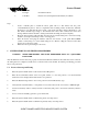
6.
Connect Bonding Lug. ( see 22 ). Use 8 AWG or larger copper conductor to connect chassis bonding lug to
the vehicle chassis.
7.
Connect the negative DC input cable to the battery negative (-) terminal. This battery negative terminal is
usually where the battery negative connects to the engine block or frame. Connect the red, positive DC input
cable to the in/line fuse near the battery positive (+) terminal. This battery terminal is usually connected to
the DC electrical system at the load side of the Battery.
4.5
AC Wiring Installation Procedure
1.
Insert the AC Input and Output connections to the mating AC connectors on the front panel of the unit, make
sure that strain relief’s “snap” when installing to prevent them from coming lose during vibration.
2.
The Vanner SRC12-1100PT has been tested with the following GFCI outlet’s:
Manufacturer Model
Hubbell GFR5252W
Hubbell GFR5252WA
Hubbell GFR5252I
Leviton 1591
Leviton 6599-I
4.6
(Optional) Remote Monitor and Control Panel Installation
Unpacking the Remote Monitor/Control Panel
Inspect the shipping container and equipment for loose, damaged, or missing parts. The remote panel
includes a 10-ft. interconnecting cable. If any damage is found, immediately notify the freight carrier.
Remote Indicator Display Description
LED
Light Display
Description
1 No Light Inverter is OFF
1 Solid Green Inverter is ON and producing AC power or Foat Charge Mode
1 Blinking Green Inverter is in Load Demand Mode or Bulk Charge Mode
System
ON
System
OFF
Fault
Standby/
Bulk Charge
Power On
AC
POWER
CONTROL
1
2