
Specifications


Owners Manual
SILENT RUNNER INVERTER/CHARGER POWER SYSTEM
15
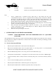
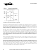
The Table below shows the recommended minimum cable size, and lug, which should be used. Wire sizing
charts published in the NEC may allow a greater amp capacity than we recommend. We have sized the cable
for a mimimum voltage drop to maintain better performance of your inverter installation. For best
performance, wire the DC negative directly back to the battery, do not use the vehicle chassis as the DC
negative conductor.
The wiring of your inverter installation should conform to the National Electric Code (NEC) and any other
state or local codes in effect at the time of installation. Article 551 of the NEC requires the overcurrent
protective device shall be installed in an accessible location on the vehicle within 18 in. (457 mm) of the
point where the power supply connects to the vehicle circuits.
Wire and Fuse Size Chart
Wire
Size
AWG
Ring Terminal
AMP or UL
recognized
equal
Max wire length, in feet, between SRC12-1100PT and battery to
keep voltage drop under 0.1 volt. The chart assumes wire carries
no other load and wire temperature is below 80ºC.
#2 322870 12
#1/0 321867 20
Fuse
Bussman Fuse
ANN200 or FS-HVBF-200
Bussman Fuse Holder 4164 (Required with ANN Style fuse)
Crimp the ring terminals using
AMP
ROTA-CRIMP 600850 (2/0 - 8ga).
AMP
Product Information Center: 800-522-6752
AMP
Tooling Assistance Center: 800-722-1111
4.4
DC Wiring Installation Procedure
Steps
1.
Make sure power to the vehicle wiring harness is disconnected. Verify that the inverter is turned OFF by
checking that the ON-OFF/RESET Inverter Switch is in the OFF-RESET position. (The button should NOT
be pushed in.)
2.
Select a location for the unit. An ideal installation location has the following characteristics:
a.
Close to the battery (usually within six feet).
b.
Protected from the weather.
c.
Well ventilated.
3.
Prepare DC cable end with appropriate terminals, verify battery positive cable is disconnected from battery.
Install cables in the following manner: Connect the positive cable to the positive DC input terminal, tighten
stud nut to a maximum of 120 lb./in. of torque, then install the protective cover with the supplied hardware.
Connect the negative cable to the negative DC input terminal, tighten stud nut to a maximum of 120 lb./in. of
torque, then install the protective cover with the supplied hardware.
4.
Route the negative and positive DC input cables from the inverter to the battery but do not connect to battery
at this time. Protect cables with grommets or other appropriate means where they may contact hard, sharp
edges throughout the installation path.
5.
Install fuse in the positive DC input cable between the battery and inverter. Fuse must be installed within 18
in. of the battery or DC wiring bus system to comply with safety agency installation requirements. Be sure