VANNER Incorporated Owner’s Manual SRC12-1200L/S Inverter/Charger Model - SRC12-1200L/S Owner's Manual - D913482 1 SRC12-1200L/S INVERTER/CHARGER 10/15/10 - 11:33 AM
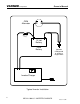
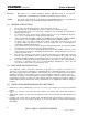
VANNER Incorporated Owner’s Manual OEM Alternator Fuse block within 18" of Battery 12 Volt Battery OEM Battery Common OEM ground at Starter or Engine Block Inverter/Charger Typical Inverter Installation 2 SRC12-1200L/S INVERTER/CHARGER 10/15/10 - 11:33 AM
VANNER Incorporated 1 2 3 4 5 6 7 8 9 10 11 Owner’s Manual Table of Contents Introduction ................................................................................................................................. 4 Specifications .............................................................................................................................. 5 Standard Features.......................................................................................................................
VANNER Incorporated 12 Owner’s Manual 11.2 Troubleshooting Procedures ..................................................................................................... 21 APPENDICES ............................................................................................................................. 23 12.1 Problem Loads .......................................................................................................................... 23 12.2 Ampere-Hour (A-H): ..........................
VANNER Incorporated Owner’s Manual 2 SPECIFICATIONS Specifications Continuous Output Power Rating Output Surge Capacity DC Input Voltage DC Input Voltage Range AC Output Voltage AC Output Frequency AC Output Wave Form DC Input Amps Inverter OFF Inverter On, in Load Demand (asleep)* Inverter ON with No AC Load Inverter ON with AC Load Battery Charger Charging Output Capacity* Bulk Voltage* Float Voltage* AC Input Voltage AC Input Current for charging Transfer Switch AC Passthrough Model SRC12-1200L/S 1,20
VANNER Incorporated Owner’s Manual 3 STANDARD FEATURES 3.1.1 True RMS regulated 120 volt ±10% AC 60 Hz Quasi-sine wave output 3.1.2 Output Short circuit / overload protection through electronic sensing 3.1.3 Input and Output circuit breakers 3.1.4 Automatic shutoff for Low Battery 3.1.5 Automatic shutoff for Overload 3.1.6 Automatic momentary shutoff/restart for Over temperature 3.1.7 Load Demand enable/disable switch 3.1.
VANNER Incorporated Owner’s Manual 1 to the OFF position can turn OFF the Load Demand Feature. This will cause the inverter to remain fully ON; producing 120 Volts AC whenever the inverter switch is ON regardless of AC load. 4.3 AUTOMATIC TRANSFER SWITCH: The Automatic Transfer Switch automatically allows input power from an external AC power source, such as shore power or a generator, to pass through the inverter output circuit for use by inverter loads.
VANNER Incorporated Owner’s Manual CAUTION DO NOT cover or obstruct ventilation openings. DO NOT mount in zero-clearance compartments. Overheating may result which may diminish system capacity. NOTICE The output of this device in not sinusoidal. The SR-SERIES inverter has a total harmonic distortion of 34.6 percent and maximum single harmonic of 24 percent. 6.3 GENERAL PRECAUTIONS 1 2 3 4 5 6 7 8 9 10 6.4 Do not expose the SR-Series Inverter to direct water spray or snow.
VANNER Incorporated 5 6 7 Owner’s Manual NEVER smoke or allow a spark of flame in the vicinity of batteries. Gases produced by batteries are explosive. Care should be taken when working with metal tools around batteries. Potentials for spark exists or short-circuit of the battery or other electrical part that may cause an explosion. Never charge a frozen battery. Battery temperature needs to be above 32°F (0°C) before charging.
VANNER Incorporated Owner’s Manual 7 COMPONENT IDENTIFICATION 15 16 17 18 AC OUTPUT IN C O R P O R A TE D INV/CHG MATING ATTACHMENT PLUG/CABLE AVAILABLE FROM PHILLIPS & TEMRO AC OUTPUT P/N: 8500641 120 VAC 60Hz FOR DISCONNECT USE ONLY - NOT FOR CURRENT INTERRUPTION 1 2 0 0 W a tt In v e r te r INVERTER CONTROL TERMINAL IFM1/REMOTE REMOTE OR IFM1 ON OFF/RESET INVERTER BATTERY LOW OVER TEMP OVER LOAD BULK/ ABSORPTION CHARGE RATE INVERTER CONTROL TERMINAL BATTERY TYPE LOAD DEMAND FLOAT 1 123
VANNER Incorporated Owner’s Manual 1 – ON/OFF/RESET PUSH BUTTON The ON/OFF Switch is a pushbutton switch used to turn the inverter function ON/OFF and is used as a RESET Switch. (Note: The charger function is controlled ON/OFF by the presence/absence of shore power.) When an automatic shutdown has occurred due to a fault, one of the fault indicator lights will be displayed until the inverter is RESET. Reset the inverter by turning the ON/OFF Switch OFF or by turning a remote switch OFF.
VANNER Incorporated Owner’s Manual Charger Indicator Lights 6 – BULK/ABSORPTION INDICATOR LIGHT (See „Battery Charger Theory of Operation‟ for battery charging performance details.) Light Action Description Blinking Yellow The unit is in Charger Mode (shore power is present) and the charger is in either the BULK STAGE or ABSORPTION STAGE of the battery charging cycle. 7 – FLOAT INDICATOR LIGHT (See „Battery Charger Theory of Operation‟ for charger performance details.
VANNER Incorporated Owner’s Manual Additional Features 15 – 120V, 60HZ @ 15A MAX. AC OUTPUT UTILIZING THE PHILLIPS & TEMRO CONNECTORS All output will be protected for ground faults by means of the Ground Fault Circuit Interrupter (GFCI) 16– 120V, 60HZ @ 15A MAX. AC OUTPUT UTILIZING GFCI CONVENIENCE RECEPTACLE 17 – 15 AMP AC OUTPUT CIRCUIT BREAKER Output CIRCUIT BREAKER (top breaker) protects AC Output at the receptacles.
VANNER Incorporated Owner’s Manual 8 INSTALLATION 8.1 UNPACKING THE INVERTER Inspect the shipping container and equipment for loose or damaged parts. If any damage is found, immediately notify the freight carrier. 8.2 INVERTER INSTALLATION CONSIDERATIONS The wiring of your inverter installation should conform to the National Electric Code (NEC) and any other state or local codes in effect at the time of installation.
VANNER Incorporated Owner’s Manual The wiring of your inverter installation should conform to the National Electric Code (NEC) and any other state or local codes in effect at the time of installation. Article 551 of the NEC requires the overcurrent protective device shall be installed in an accessible location on the vehicle within 18 in. (457 mm) of the point where the power supply connects to the vehicle circuits.
VANNER Incorporated Owner’s Manual Go back to the inverter and connect the positive DC harness to the Red connector. A spark may occur while connecting these cables. Twist the connector until it locks. 8.2.5 AC Wiring Installation Procedure Connect AC loads to the inverter GFCI receptacle. When the AC input cord is connected to shore power, shore power will pass through the GFCI receptacle.
VANNER Incorporated 8.3.1 Route the 10-ft. interface cable (011486) from the remote panel mounting area to the inverter being careful to avoid unprotected sharp corners or moving parts. 8.3.2 Turn off inverter, and then plug the interface cable into the inverter's front panel “Remote/IFM1” connector. Verify that dip Switch 4 is set to Remote. Plug the other end of the cable into the remote panel. 8.3.3 Mount the remote panel using two #8 screws.
VANNER Incorporated 13. 14. 15. 9.2 Owner’s Manual The Inverter Light on the inverter control panel has a solid green light indicating correct inverter operation. At this point, apply AC loads up to the inverter's rated capacity to verify full-power operation. Disconnect all AC loads. The Inverter Light blinks, indicating that the inverter has returned to Load Demand mode.
VANNER Incorporated Owner’s Manual 10 THEORY OF OPERATION 10.1 BATTERY CHARGER OPERATION The SRC12-1200L/S incorporates an automatic, three-stage battery charger. This design enables the unit to automatically charge batteries, maintaining the battery's integrity and reducing the likelihood of premature failure. The battery charger is designed to be used with lead-acid type batteries including sealed and gel types, but not for nickel-cadmium (Ni-Cad) or nickel-iron types.
VANNER Incorporated Figure 1 Owner’s Manual Battery Charging Graph 10.2 AUTOMATIC POWER TRANSFER SWITCH THEORY OF OPERATION The function of the Automatic Transfer Switch is to automatically accept AC input power from shore or generator, and use this power to operate inverter loads and to provide power for battery charging. Upon loss of AC input power, the transfer switch automatically switches the AC loads back to inverter power. Transfer time is approximately 30 milliseconds (0.030 seconds). The 0.
VANNER Incorporated Owner’s Manual generator) is available, the SRC12-1200L/S transfer switch system breaks the connection between neutral and inverter chassis ground. The neutral-to-ground connection for passthrough power is then provided by the AC input source. 11 PREVENTIVE MAINTENANCE There are no user serviceable components inside the inverter. For service refer to the Vanner Incorporated Service Department or other qualified service personnel. 11.
VANNER Incorporated Owner’s Manual Check the charging system for proper operation (vehicle alternator, generator). Symptom Solution OVERTEMP light illuminates. Something has caused the unit to overheat. Check for obstruction of airflow to the cooling fan or from ventilation holes. Verify AC load is within unit's rated capacity. Symptom Solution OVERLOAD light illuminates with AC load applied. Verify AC load is within unit's rated capacity.
VANNER Incorporated Owner’s Manual 12 APPENDICES 12.1 PROBLEM LOADS Although modified sine wave inverters will operate most AC loads, some loads may exhibit problems because the waveform is different than the pure sine wave of utility power. This is due to the square wave components and that the peak voltage is not quite as high as a pure sine wave.
VANNER Incorporated Owner’s Manual 12.6 DC POWER CONSUMPTION An inverter takes in DC power, and produces AC power to operate attached loads. In general, we can see a direct relationship between DC input power and AC output power. This allows us to establish the following rule: For every 10 watts of AC output power, an inverter requires one amp of DC input power on a 12 volt input inverter. Example: An inverter powering a 1,000-watt AC load requires 100 amps DC.
VANNER Incorporated Owner’s Manual Vanner Incorporated 4282 Reynolds Drive Hilliard, Ohio 43026 1-800-AC POWER (1-800-227-6937) Tel: 614-771-2718 Fax: 614-771-4904 www.vanner.com e-mail: pwrsales@vanner.