
Installation manual


www.fmiproducts.com
126336-01A18
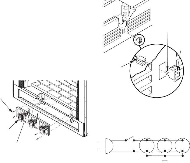
Figure 20 - Connecting Rocker Switch
ON/OFF
Rocker
Switch
Wire Harness
Connectors
Switch
Terminals
Black
110/115
V.A.C.
Blower
Motor
No. 1
Black
Hot
Nuetral
ON/OFF
Panel Switch
Blower
Motor
No. 2
Blower
Motor
No. 3
Figure 21 - BK3 Wiring Diagram
3. Connect wire connectors to rear of switch
terminals on rocker switch located in lower
louver panel (see Figure 20).
4. Check to make sure power cord is com-
pletely clear of blower and that there are
no foreign objects in blower. Also, double
check all wire leads and make sure wire
routing is not pinched or in a precarious
position. Correct accordingly.
5. Turn on power to duplex outlet if previ-
ously turned off per warning in column 2,
page 15.
6. Plug in blower power cord to duplex outlet
(see Figure 14, page 15).
7. Using ON/OFF rocker switch to turn
blower on and check for operation. Turn
blower off before continuing.
8. Peel off backing paper and stick supplied
wiring diagram decal on rebox bottom
approximately 12" in from of blower (see
Figure 18, page 17).
9. Replace all panels and/or brick bottom
panel if previously removed.
INSTALLATION
Continued
Model BK3 Installation ((V)FBL36 and
(V)FBL42 Models Only)
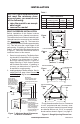
1. Place BK3 fan assembly between two leg
stands with fan blades pointing toward
rear of replace (see Figure 19).
2. Using screws provided, fasten upper
ange of blower bracket to hearth pan and
end anges to leg stands (see Figure 19).
Note: The wire assembly must be ar-
ranged in front of and away from fan
blades to reach power receptacle plug.
Figure 19 - Mounting BK3 Blower
BK3 Blower
Screws
for Leg
Stands
Screws at Upper Flange