
Installation manual


www.fmiproducts.com
126336-01A 15
INSTALLATION
Continued
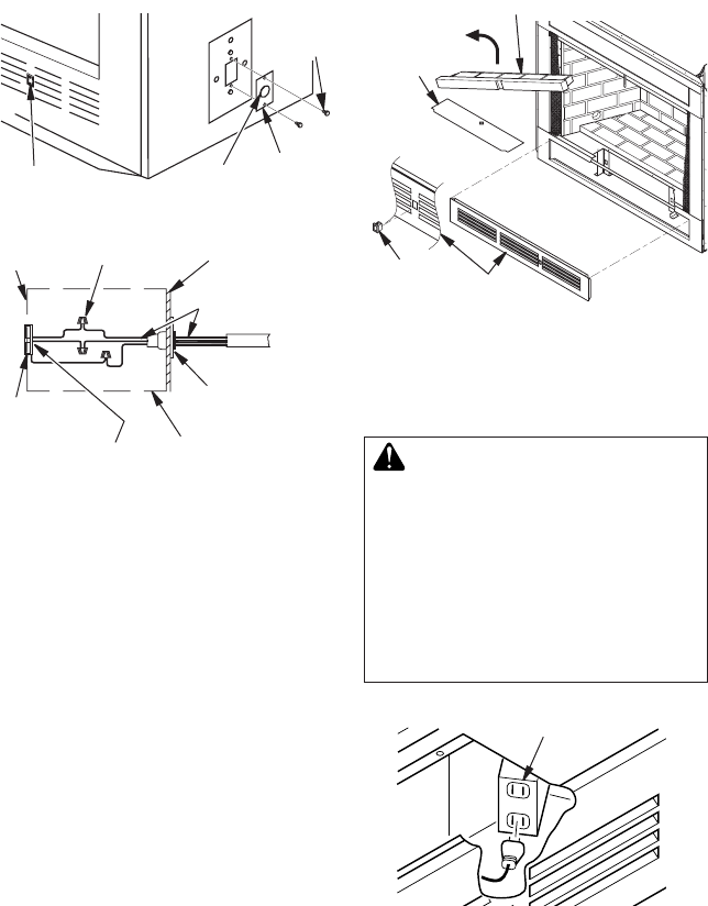
Figure 13 - Accessing Blower Compartment
(Controls Not Shown for Clarity)
Front Refractory Panel
Lower
Panel
Control
Access
Cover
ON/OFF
Rocker
Switch
Electrical
Bushing
Electrical
Cover
Plate
Rocker
Switch
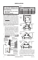
Figure 12 - Fan Switch-Electrical
Bushing
Electrical
Housing
Wire Nut (3x)
(Not Supplied)
Outer Wrapper
of Fireplace
Electrical Cover
Plate and
Electrical Bushing
Fireplace Chassis
Ground
To Power
Source
Receptacle
(Supplied)
Power Source Wiring
(Not Supplied)
Prewired Receptacle
and Ground
Sheet
Metal
Screws
Decide which way you intend to gain access
into the bottom rear of the rebox to install the
blower accessory. The lower front panel can
be removed easily by snapping out the front
with a at blade screwdriver. Use caution not
to scratch any surfaces. Models with louvered
front panels can also be removed by inserting
ngertips between slots and gently pulling out.
DO NOT FORCE. The panels are actually
held in place by means of a retention dimple
embossed on the edge of removable panels.
Accessibility to the bottom on 36" and 42"
models only, can also be gained through the
access panel underneath the bottom front
refractory brick liner. Lift the bottom front
refractory brick liner up and out of the rebox
oor, exposing the rectangular shaped access
panel (see Figure 13). The sides and back
refractory brick liner pieces do not have to
be removed. Lift access panel out by using
nger holes. Blower accessory BK or BK3 can
now be installed.
WARNING: If there is a duplex
electrical outlet installed in the
right side of the bottom of the
replace base area (see Figure
14), be sure that the electrical
power to the outlet is turned off
before proceeding with blower
installation. Failure to do this
may result in serious injury.
Duplex Electrical Outlet
Figure 14 - Accessing Duplex Electrical
Outlet Installed in Bottom Right Side of
Firebox