
Installation manual


www.fmiproducts.com
126336-01A14
INSTALLATION
Continued
INSTALLING GAS LINE
NOTICE: A qualied service per-
son must connect heater to gas
supply. Follow all local codes.
IMPORTANT: See Connecting to Gas Supply
in your log set owner’s manual for details on
gas hookup.
You may run the gas line from either side of
the rebox (see Figure 10, page 13). Decide
which side you want to run the gas line from.
Note: This is one option for installing shutoff
valve. Check local codes for equipment shut-
off valve location requirements.
Locate the recessed knockout in one of the
rebrick sidewall liners (see Figure 10 on page
13 and Figure 11). Firmly tap the center of
the knockout with a chisel until it is released.
Carefully chisel the rough edges of the hole
you have made to smooth edges. This hole
will line up with the hole in the outer casing.
CAUTION: Do not use exces-
sive force to remove the knock-
out. Too much force may damage
the rebrick concrete insert.
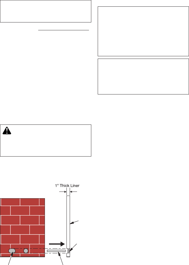
Figure 11 - Location of Knockout for
Gas Line
Knockout Chisel
Firebrick Side Wall
Remove
this Area
Side
View
INSTALLING OPTIONAL BLOWER
ACCESSORIES
NOTICE: The rebox identica-
tion label (including model num-
ber, serial number, clearances,
etc.) is located in the right side
screen pocket area on the front
of the rebox. See Figures 24
and 25, page 20.
NOTICE: If a log set is installed
in the rebox, disconnect log
set from gas supply and remove
from rebox. Contact a qualied
service person to do this.
Note: Appearance of rebox may vary de-
pending on model.
There are two (2) blower accessory options
for use in this replace. Blower accessory
models are BK available on all units and BK3
available for (V)FBL36 and (V)FBL42 series.
Model BK is a rotary squirrel cage type blower
with magnetic attachment and variable speed
control. The BK3 is a triple fan blower system
with an on/off rocker switch.
Wiring Instructions
1. Remove electrical cover plate with bush-
ing from replace by removing 2 sheet
metal screws as shown in Figure 12.
2. Slide power source wiring through
electrical bushing opening and electri-
cal cover plate and make all necessary
connections.
3. Slide all wiring connections in electrical
housing as shown in Figure 12.
4. Secure electrical cover plate with screws
previously removed.
Note: Electrical housing and cover plate have
sharp edges. Wear protective gloves.