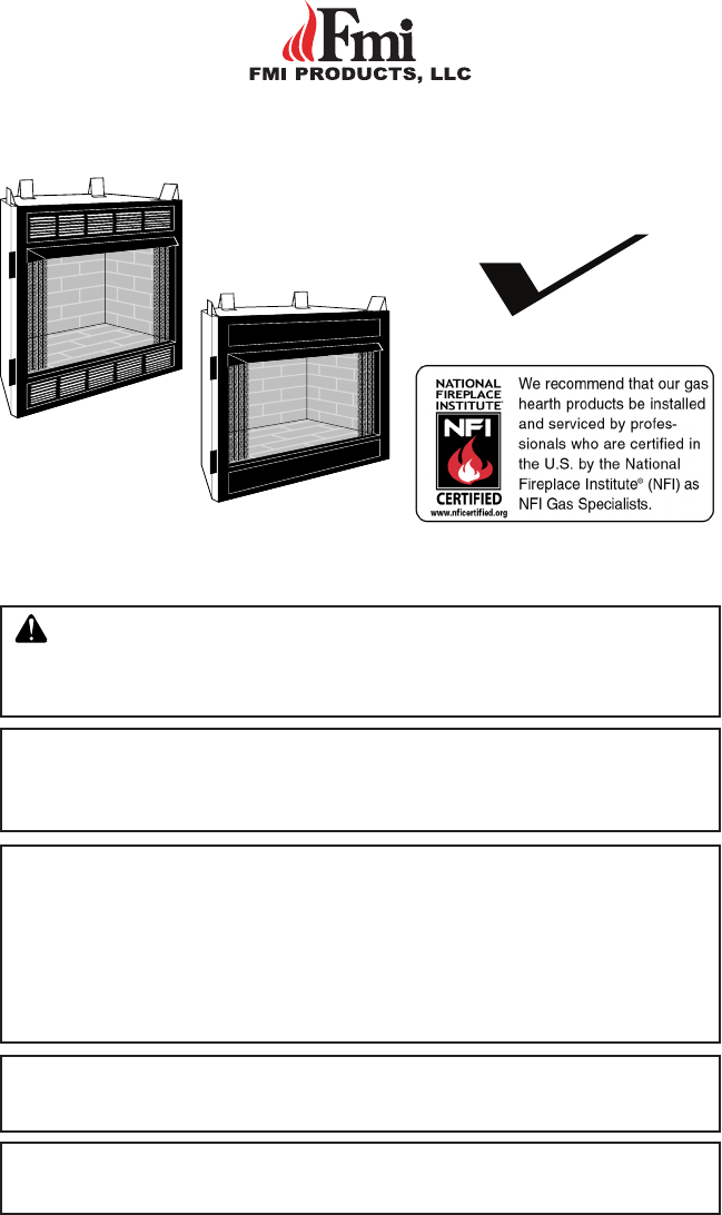
UNVENTED (VENT-FREE) UNIVERSAL FIREBOX OWNER’S OPERATION AND INSTALLATION MANUAL PFS ® US CIRCULATING MODELS: (V)FBF32, (V)FBL32, (V)FBF36, (V)FBL36, (V)FBF42, AND (V)FBL42 SERIES WARNING: If the information in this manual is not followed exactly, a fire or explosion may result causing property damage, personal injury or loss of life. FOR USE ONLY WITH A LISTED GAS-FIRED UNVENTED DECORATIVE ROOM HEATER NOT TO EXCEED 40,000 BTU/HR. DO NOT BUILD A WOOD FIRE.
TABLE OF CONTENTS Safety................................................................... 2 Local Codes......................................................... 3 Product Features.................................................. 4 Locating Firebox................................................... 4 Product Specifications.......................................... 5 Air For Combustion and Ventilation...................... 8 Installation..........................................................
SAFETY Continued Firebox front and screen become very hot when running heater. Keep children and adults away from hot surface to avoid burns or clothing ignition. Firebox will remain hot for a time after shutdown. Allow surface to cool before touching. Carefully supervise young children when they are in the room with firebox. You must operate this fireplace with the provided fireplace screen, hood if provided, in place. Make sure these parts are in place and screens are closed before running firebox.
PRODUCT FEATURES OPERATION This firebox is designed for use with approved ANSI Z21.11.2 decorative type unvented room heaters. (Physical size limitations apply. Refer to minimum firebox requirements supplied with log heater.) It requires no outside venting or chimney making installation easy and inexpensive. When used without the blower, the firebox requires no electricity making it ideal for emergency backup heat.
126336-01A www.fmiproducts.com 10.457 3.522 8.152 Outside Air Kit Location 6.991 Front View 29.373 34.451 36.361 Firebox Top View 22.444 2.534 36.503 6.870 10.517 Right Side View 3.518 8.152 7.610 Electrical Outlet 3.282 32" MODELS Left Side View 6.866 8.132 13.119 23.919 6.995 4.366 32.215 18.229 16.586 12.564 19.461 6.
www.fmiproducts.com 10.349 Outside Air Kit Location Left Side View 8.331 13.892 8.525 8.175 26.366 7.049 36.074 20.962 8.063 21.081 24.934 6.043 Front View 43.039 34.890 41.127 Firebox Top View 29.101 8.175 2.550 Right Side View 7.410 8.513 11.492 Electrical Outlet 3.277 40.
126336-01A www.fmiproducts.com 12.582 Outside Air Kit Location 10.436 Left Side View 10.768 14.233 2.523 8.153 3.120 7.083 40.037 23.964 4.479 23.216 6.028 Front View 41.896 48.136 42.000 50.045 Firebox Top View 36.143 1.360 22.281 4.359 2.315 27.117 8.153 2.520 40.035 Right Side View 7.564 10.532 13.369 Electrical Outlet 3.265 44.
AIR FOR COMBUSTION AND VENTILATION WARNING: This heater shall not be installed in a room or space unless the required volume of indoor combustion air is provided by the method described in the National Fuel Gas Code, ANSI Z223.1/NFPA 54, the International Fuel Gas Code, or applicable local codes. Read the following instructions to insure proper fresh air for this and other fuel-burning appliances in your home. Today’s homes are built more energy efficient than ever.
AIR FOR COMBUSTION AND VENTILATION Continued DETERMINING FRESH-AIR FLOW FOR HEATER LOCATION Determining if You Have a Confined or Unconfined Space Use this work sheet to determine if you have a confined or unconfined space. Space: Includes the room in which you will install heater plus any adjoining rooms with doorless passageways or ventilation grills between the rooms. 1. Determine the volume of the space (length x width x height). Length x Width x Height =_______cu. ft.
AIR FOR COMBUSTION AND VENTILATION VENTILATION AIR Ventilation Air From Inside Building This fresh air would come from an adjoining unconfined space. When ventilating to an adjoining unconfined space, you must provide two permanent openings: one within 12" of the ceiling and one within 12" of the floor on the wall connecting the two spaces (see options 1 and 2, Figure 4). You can also remove door into adjoining room (see option 3, Figure 4). Follow the National Fuel Gas Code, ANSI Z223.
INSTALLATION Continued IMPORTANT: Vent-free gas log heaters add moisture to the air. Although this is beneficial, installing firebox in rooms without enough ventilation air may cause mildew to form from too much moisture. See Air for Combustion and Ventilation, page 8. IMPORTANT: Make sure firebox is level. If firebox is not level, log set will not work properly. Note: Your firebox is designed to be used in zero clearance installations.
INSTALLATION NOTICE: If your installation does not meet the minimum clearances shown, you must do one of the following: • raise the mantel to an acceptable height • remove the mantel Table 1 Rough Opening Dimensions for Built-in Installation Front Width Depth Model (Inside to Inside) Height (Min.
INSTALLATION Continued IMPORTANT: If installing blower accessory, see Wiring Instructions, page 14. 3. Carefully set firebox in front of rough opening with back of firebox inside wall opening. IMPORTANT: If installing a perimeter trim kit, see instructions included with trim accessory. You must install shoulder screws from trim kit now. 4. Carefully insert firebox into rough opening. 5. Attach firebox to wall studs using nails or wood screws through holes in nailing flange (see Figure 9). 6.
INSTALLATION Continued INSTALLING GAS LINE NOTICE: A qualified service person must connect heater to gas supply. Follow all local codes. IMPORTANT: See Connecting to Gas Supply in your log set owner’s manual for details on gas hookup. You may run the gas line from either side of the firebox (see Figure 10, page 13). Decide which side you want to run the gas line from. Note: This is one option for installing shutoff valve. Check local codes for equipment shutoff valve location requirements.
INSTALLATION Continued Sheet Metal Screws Rocker Switch Front Refractory Panel Control Access Cover Electrical Electrical Cover Bushing Plate Electrical Wire Nut (3x) Housing (Not Supplied) Outer Wrapper of Fireplace Power Source Wiring (Not Supplied) ON/OFF Rocker Switch Lower Panel To Power Figure 13 - Accessing Blower Compartment Source (Controls Not Shown for Clarity) Electrical Cover Plate and Receptacle Electrical Bushing (Supplied) Fireplace Chassis Prewired Receptacle Ground WARNING: If the
INSTALLATION Continued Model BK Installation 1. Be certain that all wire terminals are securely attached to terminals on blower motor and that the screw retaining the green ground wire is tight (see Figure 15). 2. Place blower against lower rear wall of firebox outer wrapper with exhaust port directed upward. Depending on your model, you may have to carefully route the blower assembly past controls and brackets and position blower inside back opening.
INSTALLATION Continued Secondary Face Control Access Variable Fan Switch Lock Nut Off 1 2 Black On Control Knob 110/115 V.A.C. Black Green White Blower Motor Control Shaft Wiring Diagram Decal 12" in Front of Blower Figure 17 -Attaching Speed Control (Model May Vary From Illustration) Figure 18 - Location of Wiring Diagram Decal (Model May Vary From Illustration) 10. Check to make sure power cord is completely clear of blower wheel and there are no foreign objects in blower wheel.
INSTALLATION Continued Model BK3 Installation ((V)FBL36 and (V)FBL42 Models Only) 1. Place BK3 fan assembly between two leg stands with fan blades pointing toward rear of fireplace (see Figure 19). 2. Using screws provided, fasten upper flange of blower bracket to hearth pan and end flanges to leg stands (see Figure 19). Note: The wire assembly must be arranged in front of and away from fan blades to reach power receptacle plug.
INSTALLATION Continued OPTIONAL OUTSIDE AIR KIT (MODEL AK4/AK4F) Secure to Collars with Metal Tape, Screws or Straps (Min. of 1/4" x 20" in size) Installation of outside air kit should be performed during rough framing of fireplace due to the nature of it's location. Outside combustion air is accessed through a vented crawl space (AK4F) or through a sidewall (AK4). See Figure 22. Air Inlet Location Must Allow For Bushes or Snow CAUTION: Combustion air inlet ducts shall not terminate in attic space.
INSTALLATION Continued INSTALLING FIREPLACE HOOD AND SCREEN 1. Attach hood to firebox using screws provided (see Figure 23). 2. Insert each rod through all rings located at top of screen. 3. Insert first rod into rear hole in left side of firebox. Fasten rod to rear hole near center of firebox using #10 x 3/8" Phillips screw provided (see Figure 24). 4. Insert other rod into front hole on right side of firebox and fasten using remaining Phillips screw.
REPLACEMENT PARTS Note: Use only original replacement parts. This will protect your warranty coverage for parts replaced under warranty. Contact authorized dealers of this product. If they can’t supply original replacement part(s), call FMI PRODUCTS, LLC at 1-866-328-4537. When calling, have ready: • your name • your address • model and serial numbers of your heater • how heater was malfunctioning • purchase date Usually, we will ask you to return the part to the factory.
ACCESSORIES NOTICE: All accessories may not be available for all fireplace models. Purchase these accessories from your local dealer. If they can not supply these accessories call FMI PRODUCTS, LLC at 1-866-328-4537 for information. You can also write to the address listed on the back page of this manual.
ACCESSORIES Continued MANTELS 32" WALL MANTELS W32TU - 32" Unfinished, Traditional W32TO - 32" Oak Stain, Traditional W32CO - 32" Oak Stain, Classic W32DO - 32" Oak Stain, Dentil W32GO - 32" Oak Stain, Georgian 32" CORNER MANTELS C32TU - 32" Unfinished, Traditional C32TO - 32" Oak Stain, Traditional C32CO - 32" Oak Stain, Classic C32GO - 32" Oak Stain, Georgian 36" WALL MANTELS W36TU - 36" Unfinished, Traditional W36TO - 36" Oak Stain, Traditional 36" CORNER MANTELS C36TU - 36" Unfinished, Traditional C36
PARTS MODELS (V)FBF32, (V)FBL32, (V)FBF36, (V)FBL36, (V)FBF42 AND (V)FBL42 8 6 5 7 10 9 6 11 4 3 2 1 24 www.fmiproducts.
PARTS (V)FBF 32K (V)FBL 32K (V)FBF 32WS (V)FBL 32WS (V)FBF 36K (V)FBL 36K VFBF3 6WS VFBL3 6WS FBF36 RS FBL36 RS FBF36 RH FBL36 RH FBF36 WS-LS This list contains replaceable parts used in your firebox. When ordering parts, follow the instructions listed under Replacement Parts on page 21 of this manual. KEY NO. PART NO.
PARTS MODELS (V)FBF32, (V)FBL32, (V)FBF36, (V)FBL36, (V)FBF42 AND (V)FBL42 6 1 3 6 2 5 4 26 www.fmiproducts.
PARTS 126336-01A www.fmiproducts.
WARRANTY KEEP THIS WARRANTY Model (located on product or identification tag)______________________________ Serial No. (located on product or identification tag)___________________________ Date Purchased ___________________________ Keep receipt for warranty verification.