DigiTMR S2TM DIGITAL CIRCUIT BREAKER ANALYZER USER’S MANUAL Vanguard Instruments Company, Inc. 1520 S. Hellman Ave.
DIGITMR S2 USER’S MANUAL REV 1 SAFETY SUMMARY FOLLOW EXACT OPERATING PROCEDURES Any deviation from the procedures described in this User’s Manual may create one or more safety hazards, may damage the DigiTMR S2, or cause errors in the test results. Vanguard Instruments Company, Inc. assumes no liability for unsafe or improper use of the DigiTMR S2.
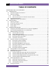
REV 1 DIGITMR S2 USER’S MANUAL TABLE OF CONTENTS CONVENTIONS USED IN THIS DOCUMENT ..................................................................................... 1 1.0 INTRODUCTION .................................................................................................................... 2 1.1 General Description and Features ................................................................................... 2 1.2 Operational Modes ..........................................................
DIGITMR S2 USER’S MANUAL REV 1 TABLE OF CONTENTS (continued) 3.9.1. Printing the Tabulated Test Results ....................................................................... 65 3.9.2. Printing the Graphic Test Results ........................................................................... 69 3.10 Working with Timing Shots ............................................................................................ 75 3.10.1. Saving Timing Shots ........................................................
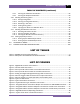
REV 1 DIGITMR S2 USER’S MANUAL LIST OF FIGURES (continued) Figure 16. Typical Tabulated Test Results Printout of an OPEN Operation .................................. 67 Figure 17. Typical Graphic Test Results Printout .......................................................................... 71 Figure 18. Expansion Graph from 0 to 200 ms ............................................................................. 72 Figure 19. Graphic Interpretation of an OPEN Timing Shot ................................
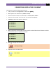
DIGITMR S2 USER’S MANUAL REV 1 CONVENTIONS USED IN THIS DOCUMENT This document uses the following conventions: • A key or switch on the DigiTMR S2 is indicated as [KEY]. • Menu options are referenced as (MENU OPTION). • Screen and menu names are referenced as “SCREEN/MENU NAME”. • The terms “test record” and “test shot” are used interchangeably. • DigiTMR S2 LCD screen output is shown as: 1. 2. 3. 4. 5.
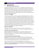
REV 1 DIGITMR S2 USER’S MANUAL 1.0 INTRODUCTION 1.1 General Description and Features The Vanguard DigiTMR S2 is an inexpensive, easy to use digital circuit breaker analyzer. The DigiTMR S2 can be operated stand-alone or can be computer-controlled. It can fully analyze a circuit-breaker’s performance by testing the contact time, stroke, velocity, over-travel, and contact wipe.
DIGITMR S2 USER’S MANUAL REV 1 Contact Timing Inputs Dry-contact input channels are used for timing circuit-breaker contacts. Each contact input channel can detect main contact and insertion-resistor contact times in milliseconds and cycles. Three contact timing channels are available on the DigiTMR S2. Breaker Stroke and Velocity One digital transducer input channel is available to measure circuit breaker contact stroke, velocity, over-travel, and bounce-back.
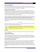
REV 1 DIGITMR S2 USER’S MANUAL Computer Interface One USB interface port and one optional Bluetooth interface is available for computer-control. Vanguard's Windows®- based Circuit Breaker Analyzer application is included with each DigiTMR S2. The software can be used to control the unit, review test records, and create circuit breaker test plans. Test records can be exported to PDF, Excel, and XML format. All future software updates can be downloaded from the Vanguard web site at no additional charge.
DIGITMR S2 USER’S MANUAL 1.2 REV 1 Operational Modes 1.2.1. “On-Line” Mode In “On-Line” mode, the trip/close time is derived from the time of trip, or close-coil initiation, to the breaker’s bushing current-break-or-make as detected by an AC clamp-on current sensing probe. The DigiTMR can time a circuit breaker’s OPEN operation by sensing the time when the OPEN coil is energized until the bushing CT current returns to zero.
REV 1 1.3 DIGITMR S2 USER’S MANUAL Technical Specifications Table 1. DigiTMR S2 Technical Specifications TYPE PHYSICAL SPECIFICATIONS INPUT POWER DRY-CONTACT INPUTS TIMING WINDOWS TIMING RESOLUTIONS TIMING ACCURACY DRY-CONTACT DETECTION RANGE RESISTOR DETECTION RANGE TRIGGER INPUT VOLTAGE Circuit-breaker analyzer 18.5"W x 14"H x 7"D (47.0 cm x 35.7cm x 17.6 cm); Weight: 20 lbs (9.
DIGITMR S2 USER’S MANUAL 1.4 REV 1 DigiTMR S2 Controls and Indicators The DigiTMR S2’s controls and indicators are shown in Figure 1 below. The purpose of the controls and indicators may seem obvious, but users should become familiar with them before using the DigiTMR S2. Accidental misuse of the controls will usually cause no serious harm. Users should also be familiar with the safety summary found on the front page of this User’s Manual. Figure 1.
REV 1 DIGITMR S2 USER’S MANUAL 2.0 PRE-TEST SETUP 2.1 Operating Voltages The DigiTMR S2 operates on voltages between 100-240 Vac, 50/60 Hz. 2.2 LCD Screen Contrast Control To increase the LCD screen contrast, press and hold the [∧] key for two seconds. To decrease the LCD screen contrast, press and hold the [∨] key for two seconds. 2.3 Printer Paper Control To advance the DigiTMR S2’s printer paper, press and release the [∧] key.
DIGITMR S2 USER’S MANUAL 2.5 REV 1 Replacing the Thermal Printer Paper The roll of thermal paper is housed inside a dispenser underneath the printer cover. To replace the paper, follow the steps below: • • • • • • • Unscrew the two large printer cover screws and remove the printer cover. Remove the leftover thermal paper roll from the paper holder. Unroll the new thermal paper roll. Feed the thermal paper into the slot between the paper pocket and the rubber roller.
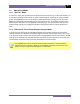
REV 1 DIGITMR S2 USER’S MANUAL 3.0 OPERATING PROCEDURES 3.1 Configuring the VCBA S2 Software for use with the DigiTMR S2 The DigiTMR S2 can be used with a PC (computer control mode) using the Vanguard Circuit Breaker Analyzer Series 2 (VCBA S2) software. From the PC, the user can time circuit breakers, retrieve test records, and create and transfer test plans to the DigiTMR S2. Follow the steps below to properly connect the DigiTMR S2 and configure the VCBA S2 application to recognize the unit. a.
DIGITMR S2 USER’S MANUAL REV 1 f. Launch the VCBA S2 application. From the “Sys-Config” menu, select “System Setup…”. The following window will be displayed: Make sure that the “Enable USB” option is UN-checked. Then, from the “Port” dropdown menu, select the COM port that corresponds to the port that the DigiTMR S2 is connected to. Then click the OK button. The VCBA S2 software will now recognize the DigiTMR S2.
REV 1 3.2 DIGITMR S2 USER’S MANUAL Connecting the DigiTMR S2 to a PC via Bluetooth The DigiTMR S2 can also be connected wirelessly to a PC using Bluetooth. To connect the unit via Bluetooth, it must first be paired with the PC. Follow the steps below to pair the DigiTMR S2 to a PC via Bluetooth: For Windows XP: a. Make sure the DigiTMR S2 is turned on. Then double click on the Bluetooth system tray icon (on the bottom right corner of your computer screen): b.
DIGITMR S2 USER’S MANUAL REV 1 The DigiTMR S2 will be listed as “DigiTmr S/N” where S/N is the device’s serial number. Click on the icon for the DigiTMR and then click on the “Next” button. d. The following window will be displayed asking for a secret key to connect to the DigiTMR S2: Type the word “default” (without the quotes and in all lower-case) and then click on the “Next” button. e.
REV 1 DIGITMR S2 USER’S MANUAL Click on the “Finish” button. g. The DigiTMR S2 will now be displayed in the “My Bluetooth Places” window: Note the port number listed under the device name. In the above case, the port number is COM14. Follow the directions in section Error! Reference source not found. to configure the VCBA S2 software to connect to the DigiTMR S2 using this COM port.
DIGITMR S2 USER’S MANUAL REV 1 For Windows 7: a. Make sure the DigiTMR S2 is turned on. Then double click on the Bluetooth system tray icon (on the bottom right corner of your computer screen): b. The “Bluetooth Devices” window will be displayed: Click on “Add a device”.
REV 1 DIGITMR S2 USER’S MANUAL c. All nearby Bluetooth devices will be listed: The DigiTMR S2 will be listed as “DigiTmr S/N” where S/N is the device’s serial number. Click on the icon for the DigiTMR and then click on the “Next” button. d. The device pairing screen will be displayed: Click on “Enter the device’s pairing code” option.
DIGITMR S2 USER’S MANUAL REV 1 e. The following window will be displayed: Type the word “default” (without the quotes and in all lower-case) in the text box and click on the “Next” button. f. The following screen will be displayed: Click on the “Close” button.
REV 1 DIGITMR S2 USER’S MANUAL g. The DigiTMR S2 will now be listed under “Bluetooth Devices”: Right click on the DigiTmr icon and select “Properties” from the pop-up menu. h. The properties window will be displayed.
DIGITMR S2 USER’S MANUAL REV 1 Note the port number listed after the device name (COM23 in the above example). Follow the directions in section Error! Reference source not found. to configure the VCBA S2 software to connect to the DigiTMR S2 using this COM port.
REV 1 3.3 DIGITMR S2 USER’S MANUAL DigiTMR S2 Cable Connections 3.3.1. Contact Cable Connections A typical contact cable connection to a circuit breaker is shown in Figure 2. Red clips are connected to phase A, B, and C of the breaker’s bushings. The black clips are connected to the ground or common side of the bushings. If the common side of the bushing is not grounded, jumpers should be installed between the bushings. NOTE It is advisable to ground one side of the contacts for most testing purposes.
DIGITMR S2 USER’S MANUAL REV 1 3.3.2. Initiate Cable Connections The DigiTMR S2 will trip or close breakers through a solid-state device which will operate on any AC or DC control voltage ranging from 10 to 300 Volts. Both the trip and close circuits are protected by 5-Ampere fuses. A typical DC trip and DC close control circuit test connection is shown in Figure 3. A typical DC trip and AC close control circuit is shown in Figure 4.
REV 1 DIGITMR S2 USER’S MANUAL Figure 4.
DIGITMR S2 USER’S MANUAL REV 1 3.3.3. Analog and Digital Voltage Monitor Connections The analog voltage input “V1” is dedicated to monitoring a breaker’s DC control voltage during an operation. The analog input records the nominal DC voltage at no load and the minimum DC voltage while the Trip or Close coil is energized. Nominal and minimum voltage readings can be printed on a tabulated report. Analog waveforms can also be plotted graphically.
REV 1 DIGITMR S2 USER’S MANUAL 3.3.4. External Trigger Input Connections The External Trigger Mode can be used to start recording when the DigiTMR S2 senses a voltage (see Figure 6). This feature can be used to time a circuit breaker without using the initiate circuit (for example, if the initiate circuit is non-operational).
DIGITMR S2 USER’S MANUAL REV 1 Figure 7.
REV 1 DIGITMR S2 USER’S MANUAL 3.3.5. AC Current Sensor Connection The DigiTMR S2 can sense a breaker’s bushing current by using a clamp-on AC current sensor connected to the breaker’s bushing CT. The AC current sensor is used in “On-Line” Mode only. The AC current sensor requires a minimum of 100 mA to operate. The maximum current is 25 Amperes. A typical AC sensor connection is shown in Figure 8. Figure 8.
DIGITMR S2 USER’S MANUAL REV 1 3.3.6. Transducer Connections A typical transducer connection is shown in Figure 9. See Appendix F for additional transducer illustrations. Figure 9.
REV 1 DIGITMR S2 USER’S MANUAL The DigiTMR S2 can also be connected to a resistor type transducer such as the ABB AHMB (see Figure 10 and Figure 11) using the Vanguard Resistor Transducer Adapter (sold separately). Figure 10. Typical Resistor Type Transducer Connection Figure 11.
DIGITMR S2 USER’S MANUAL REV 1 The DigiTMR S2 can also be connected to Doble linear and rotary transducers using the optional Vanguard Doble Transducer adapter shown below. Figure 12. Vanguard Doble Transducer Adapter Connected to a Doble TR3189 Linear Transducer Figure 13.
REV 1 3.4 DIGITMR S2 USER’S MANUAL General Procedures and Configuration The main steps for timing a circuit breaker are listed in Figure 14 below. Connect the DigiTMR S2 • Ground the DigiTMR (see note) • Connect the cables to the circuit breaker • Install the transducer and cable Apply Power • Turn on the power for the DigiTMR S2. Once the unit goes through its start-up cycle, the “Start-Up” menu will be displayed.
DIGITMR S2 USER’S MANUAL REV 1 3.4.1. Setting the Interface Language Follow the steps below to set the interface language (English, Spanish, or Turkish): a. Start from the “START-UP” menu: 1. 2. 3. 4. TIME BREAKER GET RESULTS SETUP DIAGNOSTICS Press the [3] key (SETUP). b. The following screen will be displayed: 1. 2. 3. 4. 5. ANALYSIS POINTS MEASUREMENT UNITS SAVE / RESTORE SHOT DESCRIPTION NEXT PAGE Press the [5] key (NEXT PAGE). c. The following screen will be displayed: 1. 2. 3. 4. 5. 6.
REV 1 DIGITMR S2 USER’S MANUAL ENGLISH SET Press any key to return to the “START-UP” menu.
DIGITMR S2 USER’S MANUAL REV 1 3.4.2. Setting the Measurement Units The DigiTMR S2 supports both English and Metric calculations from the breaker’s travel parameters. Follow the steps below to change the measurement units: e. Start from the “START-UP” menu: 1. 2. 3. 4. TIME BREAKER GET RESULTS SETUP DIAGNOSTICS Press the [3] key (SET-UP). f. The following screen will be displayed: 1. 2. 3. 4. 5.
REV 1 DIGITMR S2 USER’S MANUAL 2. METRIC Press the [2] key (METRIC) for Metric measurement units. The measurement units will be set to Metric, and you will be returned to the “START-UP” menu. 3. ROTARY ENCODER Press the [3] key (ROTARY ENCODER) if you would like to set the measurement units for the rotary encoder. If a rotary encoder (transducer) is used, the correct “distance/degree” value must be entered before timing the circuit breaker. NOTE The following screen will be displayed: ROTARY ENCODER 1.
DIGITMR S2 USER’S MANUAL REV 1 MM/DEGREE 47.65 MM/DEG If the value displayed is not correct, press the [CLEAR] key, and then type the desired value using the keypad. Press the [ENTER] key and you will be returned to the “START-UP” menu.
REV 1 DIGITMR S2 USER’S MANUAL 3.4.3. Setting the DigiTMR S2’s Internal Clock The DigiTMR S2 has an internal clock with a lithium battery. The battery lasts approximately three years. When a timing shot is stored, the time and date are also stored with the shot. Follow the steps below to set the unit’s internal clock: a. Start from the “START-UP” menu: 1. 2. 3. 4. TIME BREAKER GET RESULTS SETUP DIAGNOSTICS Press the [3] key (SET-UP). b. The following screen will be displayed: 1. 2. 3. 4. 5.
DIGITMR S2 USER’S MANUAL REV 1 e. The following screen will be displayed: ENTER TIME HH:MM:SS Type the time (in 24-hour format) using the keypad. The date and time will be set and you will be returned to the “START-UP” menu.
REV 1 DIGITMR S2 USER’S MANUAL 3.4.4. Entering Test Record Header Information You can enter the test record header information before performing tests. The record header includes identifying information such as the company, station, circuit, manufacturer, etc. Once the header information has been set, it will apply to all subsequent test records. Follow the steps below to enter the test header information: a. Start from the “START-UP” menu: 1. 2. 3. 4.
DIGITMR S2 USER’S MANUAL REV 1 d. The following screen will be displayed: STATION: _ ↑ /↓ TO POSITION "ENTER" TO ACCEPT Type the station name using the keypad and then press the [ENTER] key. e. The following screen will be displayed: CIRCUIT: _ ↑ /↓ TO POSITION "ENTER" TO ACCEPT Type the circuit information using the keypad and then press the [ENTER] key. f.
REV 1 DIGITMR S2 USER’S MANUAL h. The following screen will be displayed: SERIAL NUMBER: _ ↑ /↓ TO POSITION "ENTER" TO ACCEPT Type the circuit breaker’s serial number using the keypad and then press the [ENTER] key. i. The following screen will be displayed: OPERATOR: _ ↑ /↓ TO POSITION "ENTER" TO ACCEPT Type the operator’s name using the keypad and then press the [ENTER] key. All header information will be saved, and you will be returned to the “START-UP” menu.
DIGITMR S2 USER’S MANUAL REV 1 3.4.5. Setting the Frequency Follow the steps below to set the frequency (50 or 60 Hz): a. Start from the “START-UP” menu: 1. 2. 3. 4. TIME BREAKER GET RESULTS SETUP DIAGNOSTICS Press the [3] key (SET-UP). b. The following screen will be displayed: 1. 2. 3. 4. 5. ANALYSIS POINTS MEASUREMENT UNITS SAVE / RESTORE SHOT DESCRIPTION NEXT PAGE Press the [5] key (NEXT PAGE). c. The following screen will be displayed: 1. 2. 3. 4. 5. 6.
REV 1 DIGITMR S2 USER’S MANUAL 60 HZ SET Press any key to return to the “START-UP” menu.
DIGITMR S2 USER’S MANUAL REV 1 3.4.6. Setting the Default Printing Mode The DigiTMR S2 can be configured to either print the test results automatically after each test, or to print them by user request. Use the steps below to set the preferred printing method: a. Start from the “START-UP” menu: 1. 2. 3. 4. TIME BREAKER GET RESULTS SETUP DIAGNOSTICS Press the [3] key (SET-UP). b. The following screen will be displayed: 1. 2. 3. 4. 5.
REV 1 DIGITMR S2 USER’S MANUAL 1. AUTOMATIC PRINT Press the [1] key (AUTOMATIC PRINT) if you would like reports to be printed automatically after each test. The setting will be saved and you will be returned to the “START-UP” menu. 2. BY REQUEST ONLY Press the [2] key (BY REQUEST ONLY) if you do not want test reports to be printed automatically after each test. The setting will be saved and you will be returned to the “START-UP” menu. Please see section 3.9 for information on how to print test shots.
DIGITMR S2 USER’S MANUAL 3.5 REV 1 Timing Breakers in On-line Mode In On-line mode, the DigiTMR S2 can only provide OPEN or CLOSE times using the CT input channel. The DigiTMR S2 can initiate the OPEN or CLOSE tests, and then the test report will show the OPEN or CLOSE coil current reading and waveform. If the DigiTMR S2 is operated in On-line mode using the External Trigger, no coil current reading or waveform will be recorded. 3.
REV 1 3.7 DIGITMR S2 USER’S MANUAL Performing Timing Tests 3.7.1. Timing an OPEN Operation With No Insertion Resistors To time an OPEN operation with no insertion resistors: e. Start from the “START-UP” menu: 1. 2. 3. 4. TIME BREAKER GET RESULTS SETUP DIAGNOSTICS Press the [1] key (TIME BREAKER) to start a test. If a previous test shot is in the DigiTMR S2’s memory, the following screen will be displayed: PREV SHOT NOT SAVED 1. SAVE SHOT 2. CONTINUE (NO SAVE) 1.
DIGITMR S2 USER’S MANUAL REV 1 SHOT SAVED Press any key on the keypad and you will be returned to the “START-UP” menu. Re-start at step a. 2. CONTINUE (NO SAVE) If you do not wish to save the test shot in memory, press the [2] key, and then continue to step b. f. The following screen will be displayed: INSERTION RESISTOR? 1. NO 2. YES Press the [1] key (NO) to indicate that there is no insertion resistor. g. The following screen will be displayed: TIMING WINDOW: 1. WINDOW = 1 sec 2. WINDOW = 10 SEC 3.
REV 1 DIGITMR S2 USER’S MANUAL h. The following screen will be displayed: TRIGGER MODE: 1. INTERNAL TRIGGER 2. EXTERNAL TRIGGER Press the [1] key (Internal Trigger) to select the internal trigger. i. The following screen will be displayed: TIMING MODE: 1. OPEN 3. O-C 5. O-C-O 2. CLOSE 4. C-O Press the [1] key (OPEN) to select the OPEN timing operation. j.
DIGITMR S2 USER’S MANUAL NOTE REV 1 The DigiTMR S2 can be configured to print tabulated and graphic reports automatically after a test is completed. Please see section 3.4.6 for further information.
REV 1 DIGITMR S2 USER’S MANUAL 3.7.2. Timing an OPEN Operation WITH Insertion Resistors The DigiTMR S2 can time breakers with insertion resistors. The insertion resistor can range from 10 to 7,000 Ohms. Any insertion resistor greater than 7,000 Ohms is detected as an open circuit. When a breaker with insertion resistors is timed, the timing window results show the main contact timing and the insertion resistor contact timing.
DIGITMR S2 USER’S MANUAL REV 1 d. The following screen will be displayed: TIMING WINDOW: 1. WINDOW = 1 sec 2. WINDOW = 10 SEC 3. WINDOW = 20 SEC Press the [1] key (WINDOW = 1 SEC) to select the 1-second timing window. e. The following screen will be displayed: TRIGGER MODE: 1. INTERNAL TRIGGER 2. EXTERNAL TRIGGER Press the [1] key (Internal Trigger) to select the internal trigger. f. The following screen will be displayed: TIMING MODE: 1. OPEN 3. O-C 5. O-C-O 2. CLOSE 4.
REV 1 DIGITMR S2 USER’S MANUAL h. The following screen will be displayed during testing: TEST IN PROGRESS HOLD "ARM" UNTIL TEST COMPLETES. (UP TO 25 SECONDS) Continue to hold down the [ARM] switch until the test is completed. i. 52 Once the test is completed, you will be returned to the “START-UP” menu.
DIGITMR S2 USER’S MANUAL REV 1 3.7.3. Timing a CLOSE-OPEN Operation Using Contact Channel #1 The CLOSE-OPEN operation of a breaker simulates a condition where a breaker is closed on a fault. To time a CLOSE-OPEN operation: a. Start from the “START-UP” menu: 1. 2. 3. 4. TIME BREAKER GET RESULTS SETUP DIAGNOSTICS Press the [1] key (TIME BREAKER) to start a test. b. The following screen will be displayed: INSERTION RESISTOR? 1. NO 2. YES Press the [1] key (NO). c.
REV 1 DIGITMR S2 USER’S MANUAL e. The following screen will be displayed: TIMING MODE: 1. OPEN 3. O-C 5. O-C-O 2. CLOSE 4. C-O Press the [4] key (C-O) to select the CLOSE-OPEN timing operation. f. The following screen will be displayed: C-O SECOND TRIGGER 1. CONTACT #1 CLOSE 2. SET DELAY 3. NO DELAY Press the [1] key (Contact #1 CLOSE). NOTES Option details • Contact #1 CLOSE The open operation is initiated after contact channel #1 is closed.
DIGITMR S2 USER’S MANUAL REV 1 Press and hold down the [ARM] switch, and then press the [START] key. Continue to hold down the [ARM] switch. h. The following screen will be displayed during testing: TEST IN PROGRESS HOLD "ARM" UNTIL TEST COMPLETES. (UP TO 25 SECONDS) Continue to hold down the [ARM] switch until the test is completed. i. Once the test is completed, you will be returned to the “START-UP” menu.
REV 1 DIGITMR S2 USER’S MANUAL 3.7.4. Timing an OPEN-CLOSE-OPEN Operation To time an OPEN-CLOSE-OPEN operation: a. Start from the “START-UP” menu: 1. 2. 3. 4. TIME BREAKER GET RESULTS SETUP DIAGNOSTICS Press the [1] key (TIME BREAKER) to start a test. b. The following screen will be displayed: INSERTION RESISTOR? 1. NO 2. YES Press the [1] key (NO). c. The following screen will be displayed: TIMING WINDOW: 1. WINDOW = 1 sec 2. WINDOW = 10 SEC 3.
DIGITMR S2 USER’S MANUAL REV 1 e. The following screen will be displayed: TIMING MODE: 1. OPEN 3. O-C 5. O-C-O 2. CLOSE 4. C-O Press the [5] key (O-C-O) to select the OPEN-CLOSE-OPEN timing operation. f. The following screen will be displayed: O-C DELAY in MS: (10 - 350) MSEC "ENTER" WHEN DONE Using the keypad, enter the delay time (in milliseconds) between the OPEN-CLOSE operation, and then press the [ENTER] key. g.
REV 1 i. DIGITMR S2 USER’S MANUAL The following screen will be displayed during testing: TEST IN PROGRESS HOLD "ARM" UNTIL TEST COMPLETES. (UP TO 25 SECONDS) Continue to hold down the [ARM] switch until the test is completed. Once the test is completed, you will be returned to the “START-UP” menu.
DIGITMR S2 USER’S MANUAL 3.8 REV 1 Performing Diagnostic Tests 3.8.1. Performing a Slow-Close Test The DigiTMR S2 offers a unique feature called a “Slow-Close” test. This test can measure the distance of a breaker’s contact travel from the fully open position to the contact “touch” position and contact wipe, or penetration distance. The test requires the operator to manually jack the breaker’s contact from the fully open position to the fully closed position.
REV 1 DIGITMR S2 USER’S MANUAL d. The following screen will be displayed: CONTACT 1: OPEN CONTACT 2: OPEN CONTACT 3: OPEN LIFT TO CLS BRKR NOW Manually close the breaker. As each contact is closed, the screen will be updated as shown: CONTACT 1: CLOSED CONTACT 2: CLOSED CONTACT 3: OPEN LIFT TO CLS BRKR NOW After all of the contacts have been closed, the following screen will be displayed: LIFT BRKR TO CLS POS THEN PRESS "ENTER" TO FIND CONTACT WIPE LIFT TO CLS BRKR NOW Fully close the breaker.
DIGITMR S2 USER’S MANUAL REV 1 Figure 15.
REV 1 DIGITMR S2 USER’S MANUAL 3.8.2. Performing a Transducer Self-Test The transducer electronics can be checked by connecting the transducer to the DigiTMR S2 and running a “Test Transducer” diagnostic test. To test the transducer: a. Start from the “START-UP” menu: 1. 2. 3. 4. TIME BREAKER GET RESULTS SETUP DIAGNOSTICS Press the [4] key (DIAGNOSTICS). b. The following screen will be displayed: 1. 2. 3. 4. 5. 6.
DIGITMR S2 USER’S MANUAL REV 1 3.8.3. Checking Cable Hookups To check the cable hookups: a. Start from the “START-UP” menu: 1. 2. 3. 4. TIME BREAKER GET RESULTS SETUP DIAGNOSTICS Press the [4] key (DIAGNOSTICS). b. The following screen will be displayed: 1. 2. 3. 4. 5. 6. SLOW CLOSE TEST CHECK HOOKUP TEST TRANSDUCER PRINT DATA ENCODER FILTER CONTACT FILTER Press the [2] key (CHECK HOOKUP). c.
REV 1 DIGITMR S2 USER’S MANUAL A contact closure is shown as “C” on the screen and on the printout. An open contact is shown as “-” on the screen and on the printout.
DIGITMR S2 USER’S MANUAL 3.9 REV 1 Printing Test Results After a timing test has been performed, the test results can be printed in graphical or tabulated format on the DigiTMR S2’s built-in thermal printer. 3.9.1. Printing the Tabulated Test Results To print the tabulated test results from the last test performed: a. Start from the “START-UP” menu: 1. 2. 3. 4. TIME BREAKER GET RESULTS SETUP DIAGNOSTICS Press the [2] key (GET RESULTS) to get the last test results. b.
REV 1 DIGITMR S2 USER’S MANUAL d. The following screen will be displayed while the results are being printed: BUSY PRINTING A typical tabulated test results printout for an OPEN operation is shown in Figure 16. When the printer is done printing, you will be returned to the “START-UP” menu.
DIGITMR S2 USER’S MANUAL REV 1 Figure 16.
REV 1 DIGITMR S2 USER’S MANUAL Table 2. Descriptions of Tabulated Test Results Elements Item Number 68 Description 1 Contact time shown in both milliseconds and cycles. In the sample report shown in Figure 16, contact channel #1 time is 181.50 ms or 10.89 cycles. 2 Contact bounce duration (1.70 ms). 3 Contact wipe (0.77 inches). 4 Delta time - the slowest contact and fastest contact differential time (0.10 ms).
DIGITMR S2 USER’S MANUAL REV 1 3.9.2. Printing the Graphic Test Results To print the graphic test results from the last test performed: a. Start from the “START-UP” menu: 1. 2. 3. 4. TIME BREAKER GET RESULTS SETUP DIAGNOSTICS Press the [2] key (GET RESULTS) to get the last test results. b. The following screen will be displayed: 1. 2. 3. 4. PRINT TEST RESULTS PLOT FULL CHART PLOT EXPANSION PLOT 0 - 200MS Press the [2] key (PLOT FULL CHART).
REV 1 DIGITMR S2 USER’S MANUAL c. The following screen will be displayed while the graph is being printed: PLEASE WAIT PLOTTING GRAPH Figure 17 shows a CLOSE timing chart of a circuit breaker with contact activity on channels 1 and 3. A CT channel is also shown on the chart. Since the printout was generated to show both Quick-Shot Mode and Time-Travel Mode, both the CT time and Contact-Travel readings are shown on the chart.
AC Current Sensor Digital Voltage Channel V2 Analog Voltage Channel V1 Travel Trace Initiate Current Trace Contact Trace DIGITMR S2 USER’S MANUAL REV 1 Figure 17.
DIGITMR S2 USER’S MANUAL Analysis Point #2 Analysis Point #1 REV 1 Figure 18.
DIGITMR S2 USER’S MANUAL REV 1 Figure 19. Graphic Interpretation of an OPEN Timing Shot Figure 20.
REV 1 DIGITMR S2 USER’S MANUAL Figure 21.
DIGITMR S2 USER’S MANUAL 3.10 REV 1 Working with Timing Shots 3.10.1. Saving Timing Shots After performing a test, the test shot can be saved in the DigiTMR’s EEPROM or to a connected USB Flash drive by using the steps below: a. Start from the “START-UP” menu: 1. 2. 3. 4. TIME BREAKER GET RESULTS SETUP DIAGNOSTICS Press the [3] key (SETUP). b. The following screen will be displayed: 1. 2. 3. 4. 5.
REV 1 DIGITMR S2 USER’S MANUAL d. The following screen will be displayed: SAVE SHOT # 3 TEST: OPEN DATE: 07/12/12 13:25 "ENTER" TO PROCEED Press the [ENTER] key to continue. If a USB Flash drive is connected to the unit, continue to step e. If a USB Flash drive is NOT connected to the unit, continue to step f. e. The following screen will be displayed: 1. SAVE INTERNALLY 2. SAVE TO THUMB DRIVE 1. SAVE INTERNALLY Press the [1] key (SAVE INTERNALLY) to save the test record to the unit’s Flash EEPROM.
DIGITMR S2 USER’S MANUAL REV 1 The following screen will be displayed when the shot has been saved: REC_001 SAVED TO THUMB DRIVE. Press any key to return to the “START-UP” menu. f. The following screen will be displayed while the test shot is being saved: SAVE IN PROGRESS PLEASE WAIT The following screen will be displayed when the shot has been saved: SHOT SAVED Press the [ENTER] key. You will be returned to the “START-UP” menu.
REV 1 DIGITMR S2 USER’S MANUAL 3.10.2. Printing a Timing Shot Directory A listing of all the shots stored in the DigiTMR S2’s EEPROM or on a connected Flash drive can be printed on the built-in thermal printer using the steps below: a. Start from the “START-UP” menu: 1. 2. 3. 4. TIME BREAKER GET RESULTS SETUP DIAGNOSTICS Press the [3] key (SETUP). b. The following screen will be displayed: 1. 2. 3. 4. 5.
DIGITMR S2 USER’S MANUAL REV 1 1. INTERNAL DIRECTORY Press the [1] key (INTERNAL DIRECTORY) to print a directory of test shots stored in the unit’s EEPROM. Continue to step e. 2. THUMB DRIVE DIR Press the [2] key (THUMB DRIVE DIR) to print a directory of test shots stored on a connected USB Flash drive. The directory will be printed on the unit’s built-in thermal printer and you will be returned to the “START-UP” menu. A typical thumb drive directory printout is shown in Figure 22. e.
REV 1 DIGITMR S2 USER’S MANUAL Figure 22. Typical Thumb Drive Shot Directory Printout Figure 23.
DIGITMR S2 USER’S MANUAL 3.10.3. REV 1 Restoring a Test Shot Use the steps below to restore a test record from the DigiTMR S2’s internal Flash EEPROM or a connected USB Flash drive to the working memory: a. Start from the “START-UP” menu: 1. 2. 3. 4. TIME BREAKER GET RESULTS SETUP DIAGNOSTICS Press the [3] key (SETUP). b. The following screen will be displayed: 1. 2. 3. 4. 5. ANALYSIS POINTS MEASUREMENT UNITS SAVE / RESTORE SHOT DESCRIPTION NEXT PAGE Press the [3] key (SAVE / RESTORE). c.
REV 1 DIGITMR S2 USER’S MANUAL d. The following screen will be displayed: 1.INTERNAL STORAGE 2.THUMB DRIVE 1. INTERNAL STORAGE Press the [1] key (INTERNAL STORAGE) to restore a test shot from the unit’s internal Flash EEPROM. Continue to step e. 2. THUMB DRIVE Press the [2] key (THUMB DRIVE) to restore a test shot from a connected USB Flash drive. The following screen will be displayed: RESTORE THUMB DRIVE REC_ Type the record number using the keypad and then press the [ENTER] key.
DIGITMR S2 USER’S MANUAL REV 1 e. The following screen will be displayed: ENTER SHOT NUMBER TO BE RESTORED _ "ENTER" TO CONFIRM Using the numeric keypad, type the shot number that you would like to recall, and then press the [ENTER] key. If you do not know the record number, you can first print a test shot directory (see section 3.10.2). f. The following screen will be displayed: RESTORING SHOT #1 TEST: O - C - O DATE: 07/12/12 10:10 "ENTER" TO CONFIRM Press the [ENTER] key.
REV 1 DIGITMR S2 USER’S MANUAL 3.10.4. Erasing Timing Shots Use the steps below to erase (delete) timing shots from the DigiTMR’s EEPROM or from a connected USB Flash drive: a. Start from the “START-UP” menu: 1. 2. 3. 4. TIME BREAKER GET RESULTS SETUP DIAGNOSTICS Press the [3] key (SETUP). b. The following screen will be displayed: 1. 2. 3. 4. 5. ANALYSIS POINTS MEASUREMENT UNITS SAVE / RESTORE SHOT DESCRIPTION NEXT PAGE Press the [3] key (SAVE / RESTORE). c.
DIGITMR S2 USER’S MANUAL REV 1 d. The following screen will be displayed: 1. ERASE INTERNAL REC 2. ERASE THUMB DRV REC 1. ERASE INTERNAL REC Press the [1] key (ERASE INTERNAL REC) if you would like to erase test records that are stored in the unit’s internal Flash EEPROM. Continue to step e. 2. ERASE THUMB DRV REC Press the [2] key (ERASE THUMB DRV REC) if you would like to erase test records that are stored on a connected USB Flash drive. The following screen will be displayed: ERASE RECORD 1.
REV 1 DIGITMR S2 USER’S MANUAL THUMB DRIVE REC_001 ERASED! Press any key to continue. The following screen will be displayed allowing you to continue deleting additional records: ERASE RECORD 1. ERASE SINGLE REC 2. ERASE ALL RECORDS "STOP" TO EXIT Follow the steps above to erase additional records or press the [STOP] key to return to the “START-UP” menu. 2. ERASE ALL RECORDS Press the [2] key (ERASE ALL RECORDS) to erase all records from the USB Flash drive.
DIGITMR S2 USER’S MANUAL REV 1 ALL THUMB DRIVE RECORDS ERASED! Press any key to return to the “START-UP” menu. e. The following screen will be displayed: 1. ERASE SINGLE SHOT 2. ERASE ALL SHOTS! 1. ERASE SINGLE SHOT Press the [1] key (ERASE SINGLE SHOT) to erase a single test shot from the unit’s Flash EEPROM. The following screen will be displayed: ENTER SHOT NUMBER TO BE ERASED _ "ENTER" TO CONFIRM Type the record number that you would like to erase and then press the [ENTER] key.
REV 1 DIGITMR S2 USER’S MANUAL ERASE COMPLETE Press any key to return to the “START-UP” menu. 2. ERASE ALL SHOTS! Press the [2] key (ERASE ALL SHOTS!) to erase all test shots from the unit’s Flash EEPROM. The following screen will be displayed: ALL SHOTS WILL BE ERASED! "ENTER" TO CONTINUE Press the [ENTER] key to continue (you can press the [STOP] key to cancel). A progress screen will be displayed while the records are being erased.
DIGITMR S2 USER’S MANUAL 3.10.5. REV 1 Copying Test Shots to a USB Flash Drive Use the steps below to copy one or all test records from the unit’s Flash EEPROM to a connected USB Flash drive: a. Make sure a USB Flash drive is connected to the unit’s “USB MEM” port, and then start from the “START-UP” menu: 1. 2. 3. 4. TIME BREAKER GET RESULTS SETUP DIAGNOSTICS Press the [3] key (SETUP). b. The following screen will be displayed: 1. 2. 3. 4. 5.
REV 1 DIGITMR S2 USER’S MANUAL 1. COPY SINGLE RECORD Press the [1] key (COPY SINGLE RECORD) to copy a single test record from the unit’s Flash EEPROM to the connected USB Flash drive. The following screen will be displayed: ENTER RECORD NUMBER TO COPY TO FLASH DRV NUMBER: Type the record number using the keypad and then press the [ENTER] key. The selected test record will be copied to the USB Flash drive and the following screen will be displayed: REC_001 SAVED TO THUMB DRIVE.
DIGITMR S2 USER’S MANUAL 3.11 REV 1 Working with Breaker Test Plans A breaker test plan is comprised of all circuit-breaker performance specifications (stroke, velocity, and contact time).
REV 1 DIGITMR S2 USER’S MANUAL 3.11.1. Recalling a Breaker Test Plan You can recall a test plan to the working memory by using the steps below: a. Start from the “START-UP” menu: 1. 2. 3. 4. TIME BREAKER GET RESULTS SETUP DIAGNOSTICS Press the [3] key (SETUP). b. The following screen will be displayed: 1. 2. 3. 4. 5. ANALYSIS POINTS MEASUREMENT UNITS SAVE / RESTORE SHOT DESCRIPTION NEXT PAGE Press the [1] key (ANALYSIS POINTS). c. The following screen will be displayed: 1. 2. 3. 4.
DIGITMR S2 USER’S MANUAL REV 1 e. The following screen will be displayed showing the details of the first test plan stored in the unit: TEST PLAN #: 145PMI 40-20 ABB 01 "UP" OR "DOWN" TO SCROLL... "ENTER" TO SELECT If there are no test plans stored in the DigiTMR S2, the following screen will be displayed: NOTE NO TEST PLANS FOUND "ENTER" TO CONTINUE Press the [ENTER] key to return to the “START-UP” menu. You can scroll through all the test plans stored in the unit by pressing the [∧] or [∨] key.
REV 1 DIGITMR S2 USER’S MANUAL 3.11.2. Printing a Breaker Test Plan To print a breaker test plan: a. Start from the “START-UP” menu: 1. 2. 3. 4. TIME BREAKER GET RESULTS SETUP DIAGNOSTICS Press the [3] key (SETUP). b. The following screen will be displayed: 1. 2. 3. 4. 5. ANALYSIS POINTS MEASUREMENT UNITS SAVE / RESTORE SHOT DESCRIPTION NEXT PAGE Press the [1] key (ANALYSIS POINTS). c. The following screen will be displayed: 1. 2. 3. 4.
DIGITMR S2 USER’S MANUAL REV 1 e. The following screen will be displayed listing the first test plan: TEST PLAN #: 145PMI 40-20 ABB 01 "UP" OR "DOWN" TO SCROLL... "ENTER" TO SELECT Press the [∧] or [∨] key to scroll through the list of stored test plans. Press the [ENTER] key when you have found the test plan that you would like to print. f. The selected test plan will be printed and you will be returned to the “START-UP” menu. A typical test plan printout is shown in Figure 24. Figure 24.
REV 1 DIGITMR S2 USER’S MANUAL 3.11.3. Printing the Breaker Test Plan Directory Follow the steps below to print a directory of all the test plans stored in the DigiTMR S2’s EEPROM: a. Start from the “START-UP” menu: 1. 2. 3. 4. TIME BREAKER GET RESULTS SETUP DIAGNOSTICS Press the [3] key (SETUP). b. The following screen will be displayed: 1. 2. 3. 4. 5. ANALYSIS POINTS MEASUREMENT UNITS SAVE / RESTORE SHOT DESCRIPTION NEXT PAGE Press the [1] key (ANALYSIS POINTS). c.
DIGITMR S2 USER’S MANUAL REV 1 e. The test plan directory will be printed, and you will be returned to the “START-UP” menu. A sample test plan printout is shown in Figure 25. Figure 25.
REV 1 DIGITMR S2 USER’S MANUAL 3.12 Setting Up Analysis Points Analysis points are used to calculate the average contact velocity through the contact’s arc zone. The analysis points are usually specified by the breaker’s manufacturer. The user can enter the analysis points, and the DigiTMR S2 will store the two setup points for calculating velocity, one set each for the open and close operations.
DIGITMR S2 USER’S MANUAL REV 1 c. The following screen will be displayed: 1. 2. 3. 4. OPEN TIMING CLOSE TIMING PRINT SETTINGS TEST PLANS Press the [1] key (OPEN TIMING) NOTE If you would like to see the current AP1 and AP2 settings, press the [3] key (PRINT SETTINGS). The settings will be printed on the thermal printer, and you will be returned to the “START-UP” menu. d. The following screen will be displayed: OPEN ANALYSIS PT 1 1. PERCENT OF STROKE 2. DIST FROM CLOSE 3.
REV 1 DIGITMR S2 USER’S MANUAL e. The following screen will be displayed: OPEN ANALYSIS PT 1 VALUE: 1.00 IN DIST FROM CLOSE "ENTER" TO CONFIRM Press the [ENTER] key to accept the value displayed or type a different value using the keypad. Press the [ENTER] key. f. The following screen will be displayed: OPEN ANALYSIS PT 2 1. PERCENT OF STROKE 2. DIST FROM CLOSE 3. CONTACT +/- TIME Press the [2] key (DIST FROM CLOSE).
DIGITMR S2 USER’S MANUAL REV 1 g. The following screen will be displayed: OPEN ANALYSIS PT 2 VALUE: 1.00 IN DIST FROM CLOSE "ENTER" TO CONFIRM Press the [ENTER] key to accept the value displayed or type the new value using the keypad. Press the [ENTER] key. The OPEN analysis points will be set and you will be returned to the “START-UP” menu.
REV 1 DIGITMR S2 USER’S MANUAL 3.12.2. Setting Up the CLOSE Analysis Points Follow the steps below to setup the CLOSE analysis points: a. Start from the “START-UP” menu: 1. 2. 3. 4. TIME BREAKER GET RESULTS SETUP DIAGNOSTICS Press the [3] key (SETUP). b. The following screen will be displayed: 1. 2. 3. 4. 5. ANALYSIS POINTS MEASUREMENT UNITS SAVE / RESTORE SHOT DESCRIPTION NEXT PAGE Press the [1] key (ANALYSIS POINTS). c. The following screen will be displayed: 1. 2. 3. 4.
DIGITMR S2 USER’S MANUAL REV 1 e. The following screen will be displayed: CLOSE ANALYSIS PT 1 VALUE: 1.00 IN DIST FROM CLOSE "ENTER" TO CONFIRM Press the [ENTER] key to accept the value displayed or type a different value using the keypad. Press the [ENTER] key. f. The following screen will be displayed: CLOSE ANALYSIS PT 2 1. PERCENT OF STROKE 2. DIST FROM CLOSE 3. CONTACT +/- TIME Press the [2] key (DIST FROM CLOSE). g. The following screen will be displayed: CLOSE ANALYSIS PT 2 VALUE: 1.
REV 1 4.0 DIGITMR S2 USER’S MANUAL GLOSSARY OF TERMS Breaker Bounce-Back Distance Bounce-back is the distance the breaker contact moves before the resting position after the over-travel. Bounce-back is typically found in the close operation. Breaker Over-Travel Distance Over-travel is the distance the contact moves beyond the resting position. Over-travel is typically found in the close operation.
DIGITMR S2 USER’S MANUAL 5.0 REV 1 DIGITMR S2 TROUBLE-SHOOTING GUIDE PROBLEM DESCRIPTION Possible Causes and Suggested Solutions The DigiTMR S2 will neither trip nor close the breaker. • Make sure you hold the “ARM” switch down during each test. • Check the OPEN or CLOSE fuses. • Check the initiate leads. For a “Positive Trip” circuit, one Close lead and one Open lead should be connected to the Positive side of the power supply. • Check the initiate leads.
REV 1 DIGITMR S2 USER’S MANUAL No “PASS” or “FAIL” indicators on the tabulated report. • Test plan was not loaded before performing a test. Load a test plan and then re-print the tabulated report. How does one review the current analysis setting? • From the “START-UP” menu, press the [3] key (SETUP). • Press the [1] key (ANALYSIS POINTS). • Press the [3] key (PRINT SETTINGS). The current AP1 & AP2 settings will be printed.
DIGITMR S2 USER’S MANUAL REV 1 APPENDIX Appendix A. ITE Circuit Breaker Model 14.4K Timing Chart AP1 = 1.5” AP2 = 3.
REV 1 DIGITMR S2 USER’S MANUAL Appendix B. DigiTMR S2 Test Plan for ITE Circuit Breaker Model 14.
DIGITMR S2 USER’S MANUAL REV 1 Appendix C. DigiTMR S2 Timing Chart for ITE Circuit Breaker Model 14.
REV 1 DIGITMR S2 USER’S MANUAL Appendix D. DigiTMR S2 Timing Chart for ITE Circuit Breaker Model 14.
DIGITMR S2 USER’S MANUAL REV 1 Appendix E.
REV 1 DIGITMR S2 USER’S MANUAL Appendix F.
DIGITMR S2 USER’S MANUAL REV 1 Figure 26. Linear Transducer on an OCB Figure 27.
REV 1 DIGITMR S2 USER’S MANUAL Figure 28. Rotary Transducer on ABB HMB Mech Figure 29.
DIGITMR S2 USER’S MANUAL REV 1 Figure 30. ABB 72PM Circuit Breaker with Linear Transducer and Special Timing Rod Figure 31.
REV 1 DIGITMR S2 USER’S MANUAL Figure 32. Rotary Transducer on Federal Pacific Breaker Figure 33.
DIGITMR S2 USER’S MANUAL REV 1 Figure 34. Linear Transducer on Areva DT1-72.
1520 S. Hellman Ave • Ontario, CA 91761 • USA Phone: 909-923-9390 • Fax: 909-923-9391 www.vanguard-instruments.com Copyright © 2012 by Vanguard Instruments Company, Inc. DigiTMR S2 User’s Manual • Revision 1.