DigiTMR S2 PCTM DIGITAL CIRCUIT BREAKER ANALYZER USER’S MANUAL Vanguard Instruments Company, Inc. 1520 S. Hellman Ave.
DIGITMR S2 PC USER’S MANUAL REV 1 SAFETY SUMMARY FOLLOW EXACT OPERATING PROCEDURES Any deviation from the procedures described in this User’s Manual may create one or more safety hazards, may damage the DigiTMR S2 PC, or cause errors in the test results. Vanguard Instruments Company, Inc. assumes no liability for unsafe or improper use of the DigiTMR S2 PC.
REV 1 DIGITMR S2 PC USER’S MANUAL TABLE OF CONTENTS 1.0 INTRODUCTION .................................................................................................................... 1 1.1 General Description and Features ................................................................................... 1 1.2 Operational Modes .......................................................................................................... 3 1.2.1. “On-Line” Mode ..............................................
DIGITMR S2 PC USER’S MANUAL 1.0 INTRODUCTION 1.1 General Description and Features REV 1 The Vanguard DIGITMR S2 PC is an inexpensive, easy to use digital circuit breaker analyzer that is designed to be used with a PC. This inexpensive analyzer offers the most cost-effective method for testing circuit breakers. It can fully analyze a circuit-breaker’s performance by testing the contact time, stroke, velocity, over-travel, and contact wipe.
REV 1 DIGITMR S2 PC USER’S MANUAL CT Input One non-contact AC current sensor is used to monitor circuit breaker on-line current for the “on-line” timing mode. Voltage Monitoring Input One analog input channel, designated as (V1), is dedicated to monitoring the substation DC supply or coil voltage (0-255 Volts, DC or peak AC). A second voltage input channel, designated as V2, is dedicated to detecting voltage On/Off status (presence or absence).
DIGITMR S2 PC USER’S MANUAL 1.2 REV 1 Operational Modes 1.2.1. “On-Line” Mode In “On-Line” mode, the trip/close time is derived from the time of trip, or close-coil initiation, to the breaker’s bushing current-break-or-make as detected by an AC clamp-on current sensing probe. The DigiTMR S2 PC can time a circuit breaker’s OPEN operation by sensing the time when the OPEN coil is energized until the bushing CT current returns to zero.
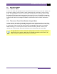
REV 1 1.3 DIGITMR S2 PC USER’S MANUAL Technical Specifications Table 1. DigiTMR S2 PC Technical Specifications TYPE PHYSICAL SPECIFICATIONS INPUT POWER DRY-CONTACT INPUTS TIMING WINDOWS TIMING RESOLUTIONS TIMING ACCURACY DRY-CONTACT DETECTION RANGE RESISTOR DETECTION RANGE TRIGGER INPUT VOLTAGE Portable digital circuit breaker analyzer 18.5"W x 14"H x 7"D (47.0 cm x 35.7cm x 17.6 cm); Weight: 16 lbs (7.
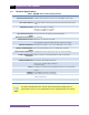
DIGITMR S2 PC USER’S MANUAL 1.4 REV 1 DigiTMR S2 PC Controls and Indicators The DigiTMR S2 PC’s controls and indicators are shown in Figure 1 below. The purpose of the controls and indicators may seem obvious, but users should become familiar with them before using the DigiTMR S2 PC. Accidental misuse of the controls will usually cause no serious harm. Users should also be familiar with the safety summary found on the front page of this User’s Manual. Figure 1.
REV 1 DIGITMR S2 PC USER’S MANUAL 2.0 OPERATING PROCEDURES 2.1 Configuring the VCBA S2 Software for use with the DigiTMR S2 PC The DigiTMR S2 PC is operated using the Vanguard Circuit Breaker Analyzer Series 2 (VCBA S2) PC software. Follow the steps below to properly connect the DigiTMR S2 PC and configure the VCBA S2 application to recognize the unit. a. Install the VCBA S2 software (please see the VCBA S2 software user’s manual for details) b.
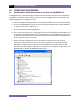
DIGITMR S2 PC USER’S MANUAL REV 1 f. Launch the VCBA S2 application. From the “Sys-Config” menu, select “System Setup…”. The following window will be displayed: Make sure that the “Enable USB” option is UN-checked. Then, from the “Port” dropdown menu, select the COM port that corresponds to the port that the DigiTMR S2 PC is connected to. Then click the OK button. The VCBA S2 software will now recognize the DigiTMR S2 PC.
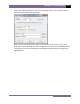
REV 1 2.2 DIGITMR S2 PC USER’S MANUAL Connecting the DigiTMR S2 PC to a PC via Bluetooth The DigiTMR S2 PC can also be connected wirelessly to a PC using Bluetooth (if the Bluetooth option is installed). To connect the unit via Bluetooth, it must first be paired with the PC. Follow the steps below to pair the DigiTMR S2 PC to a PC via Bluetooth: For Windows XP: a. Make sure the DigiTMR S2 PC is turned on.
DIGITMR S2 PC USER’S MANUAL REV 1 The DigiTMR S2 PC will be listed as “DigiTmr S/N” where S/N is the device’s serial number. Click on the icon for the DigiTMR S2 PC and then click on the “Next” button. d. The following window will be displayed asking for a secret key to connect to the DigiTMR S2 PC: Type the word “default” (without the quotes and in all lower-case) and then click on the “Next” button. e.
REV 1 DIGITMR S2 PC USER’S MANUAL f. The following confirmation screen will be displayed: Click on the “Finish” button. g. The DigiTMR S2 PC will now be displayed in the “My Bluetooth Places” window: Note the port number listed under the device name. In the above case, the port number is COM14. Follow the directions in section Error! Reference source not found. to configure the VCBA S2 software to connect to the DigiTMR S2 PC using this COM port.
DIGITMR S2 PC USER’S MANUAL REV 1 For Windows 7: a. Make sure the DigiTMR S2 PC is turned on. Then double click on the Bluetooth system tray icon (on the bottom right corner of your computer screen): b. The “Bluetooth Devices” window will be displayed: Click on “Add a device”.
REV 1 DIGITMR S2 PC USER’S MANUAL c. All nearby Bluetooth devices will be listed: The DigiTMR S2 PC will be listed as “DigiTmr S/N” where S/N is the device’s serial number. Click on the icon for the DigiTMR S2 PC and then click on the “Next” button. d. The device pairing screen will be displayed: Click on “Enter the device’s pairing code” option.
DIGITMR S2 PC USER’S MANUAL REV 1 e. The following window will be displayed: Type the word “default” (without the quotes and in all lower-case) in the text box and click on the “Next” button. f. The following screen will be displayed: Click on the “Close” button.
REV 1 DIGITMR S2 PC USER’S MANUAL g. The DigiTMR S2 PC will now be listed under “Bluetooth Devices”: Right click on the DigiTmr S2 PC icon and select “Properties” from the pop-up menu. h. The properties window will be displayed.
DIGITMR S2 PC USER’S MANUAL REV 1 Note the port number listed after the device name (COM23 in the above example). Follow the directions in section Error! Reference source not found. to configure the VCBA S2 software to connect to the DigiTMR S2 PC using this COM port.
REV 1 2.3 DIGITMR S2 PC USER’S MANUAL DigiTMR S2 PC Cable Connections 2.3.1. Contact Cable Connections A typical contact cable connection to a circuit breaker is shown in Figure 2. Red clips are connected to phase A, B, and C of the breaker’s bushings. The black clips are connected to the ground or common side of the bushings. If the common side of the bushing is not grounded, jumpers should be installed between the bushings.
DIGITMR S2 PC USER’S MANUAL REV 1 2.3.2. Initiate Cable Connections The DigiTMR S2 PC will trip or close breakers through a solid-state device which will operate on any AC or DC control voltage ranging from 10 to 300 Volts. Both the trip and close circuits are protected by 5-Ampere fuses. A typical DC trip and DC close control circuit test connection is shown in Figure 3. A typical DC trip and AC close control circuit is shown in Figure 4.
REV 1 DIGITMR S2 PC USER’S MANUAL Figure 4.
DIGITMR S2 PC USER’S MANUAL REV 1 2.3.3. Analog and Digital Voltage Monitor Connections The analog voltage input “V1” is dedicated to monitoring a breaker’s DC control voltage during an operation. The analog input records the nominal DC voltage at no load and the minimum DC voltage while the Trip or Close coil is energized. Nominal and minimum voltage readings can be printed on a tabulated report. Analog waveforms can also be plotted graphically.
REV 1 DIGITMR S2 PC USER’S MANUAL 2.3.4. External Trigger Input Connections The External Trigger Mode can be used to start recording when the DigiTMR S2 PC senses a voltage (see Figure 6). This feature can be used to time a circuit breaker without using the initiate circuit (for example, if the initiate circuit is non-operational).
DIGITMR S2 PC USER’S MANUAL REV 1 Figure 7.
REV 1 DIGITMR S2 PC USER’S MANUAL 2.3.5. AC Current Sensor Connection The DigiTMR S2 PC can sense a breaker’s bushing current by using a clamp-on AC current sensor connected to the breaker’s bushing CT. The AC current sensor is used in “On-Line” Mode only. The AC current sensor requires a minimum of 100 mA to operate. The maximum current is 25 Amperes. A typical AC sensor connection is shown in Figure 8. Figure 8.
DIGITMR S2 PC USER’S MANUAL REV 1 2.3.6. Transducer Connections A typical transducer connection is shown in Figure 9. Figure 9.
REV 1 DIGITMR S2 PC USER’S MANUAL The DigiTMR S2 PC can also be connected to a resistor type transducer such as the ABB AHMB (see Figure 10 and Figure 11) using the Vanguard Resistor Transducer Adapter (sold separately). Figure 10. Typical Resistor Type Transducer Connection Figure 11.
DIGITMR S2 PC USER’S MANUAL REV 1 The DigiTMR S2 PC can also be connected to Doble linear and rotary transducers using the optional Vanguard Doble Transducer adapter shown below. Figure 12. Vanguard Doble Transducer Adapter Connected to a Doble TR3189 Linear Transducer Figure 13.
REV 1 3.0 DIGITMR S2 PC USER’S MANUAL GLOSSARY OF TERMS Breaker Bounce-Back Distance Bounce-back is the distance the breaker contact moves before the resting position after the over-travel. Bounce-back is typically found in the close operation. Breaker Over-Travel Distance Over-travel is the distance the contact moves beyond the resting position. Over-travel is typically found in the close operation.
DIGITMR S2 PC USER’S MANUAL 4.
1520 S. Hellman Ave • Ontario, CA 91761 • USA Phone: 909-923-9390 • Fax: 909-923-9391 www.vanguard-instruments.com Copyright © 2012 by Vanguard Instruments Company, Inc. DigiTMR S2 PC User’s Manual • Revision 1.