
Manual

REV 1 CT-7000 S3 USER’S MANUAL
10
3.0 OPERATING PROCEDURES
3.1 Cable Connections
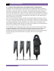
3.1.1. Contact Cable Connections
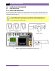
A typical contact cable connection to a circuit breaker is shown in Figure 2. Red and black clips
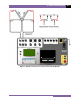
are connected across the circuit contact phases A, B, and C. A typical circuit breaker with series
contacts is shown in Figure 3.
NOTE
It is advisable to ground one side of the contacts for most testing purposes. If a
breaker is floating or un-grounded, ensure that the contact channel inputs are
protected against static discharge.
Figure 2. Typical 3-Phase Circuit Breaker Connections