CT-7000 S3 DIGITAL CIRCUIT BREAKER ANALYZER USER’S MANUAL Vanguard Instruments Company, Inc. 1520 S. Hellman Ave.
CT-7000 S3 USER’S MANUAL REV 1 SAFETY SUMMARY FOLLOW EXACT OPERATING PROCEDURES Any deviation from the procedures described in this User’s Manual may create one or more safety hazards, may damage the CT-7000 S3, or cause errors in the test results. Vanguard Instruments Company, Inc. assumes no liability for unsafe or improper use of the CT-7000 S3.
REV 1 CT-7000 S3 USER’S MANUAL TABLE OF CONTENTS CONVENTIONS USED IN THIS DOCUMENT ..................................................................................... 1 1.0 INTRODUCTION .................................................................................................................... 2 1.1 General Description and Features ................................................................................... 2 1.2 Optional Features ..........................................................
CT-7000 S3 USER’S MANUAL REV 1 3.4.5. Restoring a Test Record from a USB Flash Drive .................................................... 83 3.4.6. Copying Test Records to a USB Flash Drive ............................................................ 85 3.4.7. Deleting Test Records from the Flash EEPROM ..................................................... 87 3.4.8. Deleting Test Records from a USB Flash Drive ....................................................... 90 3.5 Working With Test Plans .........
REV 1 CT-7000 S3 USER’S MANUAL LIST OF FIGURES Figure 1. CT-7000 S3 Controls and Indicators ................................................................................. 6 Figure 2. Typical 3-Phase Circuit Breaker Connections ................................................................ 10 Figure 3. Typical Connections for Series Contact Circuit Breaker ................................................ 11 Figure 4. Typical DC Trip and DC Close Control Circuit Connection .............................
CT-7000 S3 USER’S MANUAL REV 1 CONVENTIONS USED IN THIS DOCUMENT This document uses the following conventions: • A key or switch on the CT-7000 S3 is indicated as [KEY] and [SWITCH]. • Menu options are referenced as (MENU OPTION). • Screen and menu names are referenced as “SCREEN/MENU NAME”. • The terms “test record” and “test shot” are used interchangeably. • CT-7000 S3 LCD screen output is shown as: 1. 2. 3. 4. 5.
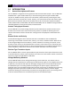
REV 1 CT-7000 S3 USER’S MANUAL 1.0 INTRODUCTION 1.1 General Description and Features The CT-7000 S3 is Vanguard's fourth generation EHV circuit breaker analyzer. The CT-7000 S3 is available with 3 (part number 9021-UC) or 6 contact timing channels (part number 9100UC).The CT-7000 S3 can fully analyze a circuit breaker's performance by measuring the main contact and resistor contact time, stroke, velocity, over-travel, bounce back and contact wipes.
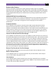
CT-7000 S3 USER’S MANUAL REV 1 Breaker Initiate Features A built-in solid-state initiate device is used to operate a breaker from the CT-7000 S3. Operational modes include OPEN, CLOSE, OPEN-CLOSE, CLOSE-OPEN, and OPEN-CLOSE-OPEN. Multiple operation like OPEN-CLOSE, CLOSE-OPEN, and OPEN-CLOSE-OPEN can be initiated by using a programmable delay time (in milliseconds) or by sensing a specific breaker contact condition.
REV 1 CT-7000 S3 USER’S MANUAL Diagnostic Capabilities The CT-7000 S3 can perform diagnostics on its internal electronics. Diagnostics can be performed to verify contact cable connections and to test the travel transducer’s electronics. 1.2 Optional Features “On-line” Timing Mode In addition to the conventional off-line timing mode, the CT-7000 S3 also offers an optional three-phase “on-line” timing mode.
CT-7000 S3 USER’S MANUAL 1.3 REV 1 Technical Specifications Table 1.
REV 1 1.4 CT-7000 S3 USER’S MANUAL CT-7000 S3 Controls and Indicators The CT-7000 S3’s controls and indicators are shown in Figure 1 below. A leader line with an index number points to each control and indicator, which is cross-referenced to a functional description in Table 2. The table describes the function of each item on the control panel. The purpose of the controls and indicators may seem obvious, but users should become familiar with them before using the CT-7000 S3.
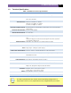
CT-7000 S3 USER’S MANUAL REV 1 Table 2. Functional Descriptions of CT-7000 S3 Controls and Indicators Item Number Panel Markings Functional Description 1 CONTACT INPUT (C1-C6) 2 T1, T2, T3 Digital travel transducer channels (16-pin connectors). 3 R1, R2, R3 Resistor type transducer inputs (5-pin). 4 V1 5 V2, V3 V2 and V3 voltage input channels dedicated to detecting voltage absence or presence. Voltage input ranges from 24-255 V DC or peak AC.
REV 1 CT-7000 S3 USER’S MANUAL 2.0 PRE-TEST SETUP 2.1 LCD Screen Contrast Control To increase the LCD screen contrast, press and hold the [] key for two seconds. Release the button when the desired contrast level has been reached. To decrease the LCD screen contrast, press and hold the [] key for two seconds. Release the button when the desired contrast level has been reached. 2.2 Printer Paper Control To advance the thermal printer paper, press and release the [] key.
CT-7000 S3 USER’S MANUAL 2.4 REV 1 Replacing the Thermal Printer Paper The roll of thermal paper is housed inside a dispenser underneath the printer cover. To replace the paper, follow the steps below: • • • • • • • Unscrew the two large printer cover screws and remove the printer cover. Remove the leftover thermal paper roll from the paper holder. Unroll the new thermal paper roll. Feed the thermal paper into the slot between the paper pocket and the rubber roller.
REV 1 CT-7000 S3 USER’S MANUAL 3.0 OPERATING PROCEDURES 3.1 Cable Connections 3.1.1. Contact Cable Connections A typical contact cable connection to a circuit breaker is shown in Figure 2. Red and black clips are connected across the circuit contact phases A, B, and C. A typical circuit breaker with series contacts is shown in Figure 3. NOTE It is advisable to ground one side of the contacts for most testing purposes.
CT-7000 S3 USER’S MANUAL REV 1 Figure 3.
REV 1 CT-7000 S3 USER’S MANUAL 3.1.2. Initiate Cable Connections The CT-7000 S3 can trip or close breakers through a solid-state device operating on any AC or DC control voltage ranging from 10 to 300 Volts. Both the trip and close circuits are protected by 5 Ampere fuses. A typical DC trip and DC close control circuit connection is shown in Figure 4. A typical DC trip and AC close control circuit connection is shown in Figure 5. Figure 4.
CT-7000 S3 USER’S MANUAL REV 1 Figure 5.
REV 1 CT-7000 S3 USER’S MANUAL 3.1.3. Online Timing Connections (with optional Online Timing feature) In addition to the conventional off-line timing mode, the CT-7000 S3 also offers an optional three-phase “on-line” timing mode. In this mode, the CT-7000 S3 captures the breaker’s trip or close time, the trip/close coil current “fingerprint”, the battery supply voltage, and auxiliary switch times while the breaker is still in service.
CT-7000 S3 USER’S MANUAL REV 1 Figure 7.
REV 1 CT-7000 S3 USER’S MANUAL 3.1.4. Dual Ground Connections (with optional Dual Ground feature) With the optional dual ground testing mode, the CT-7000 S3 can measure a CB contact time with ground being applied to both sides of the bushings. The clamp-on probe is connected to one side of the CB safety ground straps, and an AC signal is coupled to this strap. A sensor on the probe will detect a change in the induced AC signal when the CB contact is opened or closed.
CT-7000 S3 USER’S MANUAL REV 1 3.1.5. Analog and Digital Voltage Monitoring Connections The analog voltage input “V1” can monitor a breaker’s DC control voltage during an operation. The analog voltage input records the nominal DC voltage at no load and the minimum DC voltage while the Trip or Close coil is energized. The nominal and minimal voltage readings are printed on a tabulated report, and the analog waveforms are plotted in graphical format.
REV 1 CT-7000 S3 USER’S MANUAL 3.1.6. External Trigger Input Connections The External Trigger Mode can be used to start recording data when the CT-7000 S3 senses a voltage. A typical application for the External Trigger Mode is to time a circuit breaker in a Close operation and to start timing only when the Close coil is energized, thus bypassing the 52X relay delay time.
CT-7000 S3 USER’S MANUAL REV 1 3.1.7. Digital Transducer Connection A typical digital transducer connection is shown in Figure 11. Figure 11.
REV 1 CT-7000 S3 USER’S MANUAL 3.1.8. Resistor Type Transducer Connection The CT-7000 S3 provides three channels for resistor type transducers. The transducer resistance input can range from 200 Ohms to 10K Ohms. The CT-7000 S3 supplies a 5 Vdc reference voltage to power the resistor type transducer. The sense voltage is translated into a travel distance based on the transducer calibration parameters. The user is required to setup the resistor transducer before performing a test.
CT-7000 S3 USER’S MANUAL 3.2 REV 1 Changing Setup Parameters 3.2.1. Entering Test Record Header Information You can enter the test record header information before performing tests. The record header includes identifying information such as the company, station, circuit, model number, etc. Once the header information has been entered, it will apply to all subsequent test records. To enter the header information: a.
REV 1 CT-7000 S3 USER’S MANUAL d. The following screen will be displayed: STATION: _ ↑↓ to position "ENTER" TO ACCEPT Type the station name using the keypad and then press the [ENTER] key. e. The following screen will be displayed: CIRCUIT: _ ↑↓ to position "ENTER" TO ACCEPT Type the circuit information using the keypad and then press the [ENTER] key. f.
CT-7000 S3 USER’S MANUAL REV 1 h. The following screen will be displayed: SERIAL NUMBER: _ ↑↓ to position "ENTER" TO ACCEPT Type the circuit breaker serial number using the keypad and then press the [ENTER] key. i. The following screen will be displayed: OPERATOR: _ ↑↓ to position "ENTER" TO ACCEPT Type the operator’s name using the keypad and then press the [ENTER] key. All header information will be saved, and you will be returned to the “START-UP” menu.
REV 1 CT-7000 S3 USER’S MANUAL 3.2.2. Setting the Clock Follow the steps below to set the CT-7000 S3’s internal clock: a. Start from the “START-UP” menu: 1. 2. 3. 4. 5. TIME BREAKER 09/12/13 GET RESULTS 10:10:10 SAVE/RESTORE SETUP DIAGNOSTICS Press the [4] key (SETUP). b. The following screen will be displayed: 1. 2. 3. 4. 5. ANALYSIS POINTS MEASUREMENT UNITS SHOT DESCRIPTION NUMBER OF CHANNELS NEXT PAGE Press the [5] key (NEXT PAGE). c. The following screen will be displayed: 1. 2. 3. 4. 5. 6.
CT-7000 S3 USER’S MANUAL REV 1 3.2.3. Configuring Automatic or Manual Printing of Test Results The CT-7000 S3 can be configured to print graphs and tabulated results automatically or manually after each test. To configure the printing method: a. Start from the “START-UP” menu: 1. 2. 3. 4. 5. TIME BREAKER 09/12/13 GET RESULTS 10:10:10 SAVE/RESTORE SETUP DIAGNOSTICS Press the [4] key (SETUP). b. The following screen will be displayed: 1. 2. 3. 4. 5.
REV 1 CT-7000 S3 USER’S MANUAL 3.2.4. Setting the Units of Measure The CT-7000 S3 supports and displays both English and Metric calculations. You can switch between the English and Metric systems using the steps below: a. Start from the “START-UP” menu: 1. 2. 3. 4. 5. TIME BREAKER 09/12/13 GET RESULTS 10:10:10 SAVE/RESTORE SETUP DIAGNOSTICS Press the [4] key (SETUP). b. The following screen will be displayed: 1. 2. 3. 4. 5.
CT-7000 S3 USER’S MANUAL REV 1 3.2.5. Setting the OPEN Timing Analysis Points Two analysis points are used to calculate the velocity of the circuit breaker in the OPEN operation. To configure the OPEN timing analysis points: a. Start from the “START-UP” menu: 1. 2. 3. 4. 5. TIME BREAKER 09/12/13 GET RESULTS 10:10:10 SAVE/RESTORE SETUP DIAGNOSTICS Press the [4] key (SETUP). b. The following screen will be displayed: 1. 2. 3. 4. 5.
REV 1 CT-7000 S3 USER’S MANUAL Percentage of stroke is the distance based upon the percentage of the total breaker’s stroke distance. The distance is always measured from the starting NOTE point at the fully closed position of the breaker contacts. The following screen will be displayed: OPEN ANALYSIS PT 1 % of total stroke 00% "ENTER" TO CONFIRM Type the percentage value using the keypad and then press the [ENTER] key. Continue to step e. 2.
CT-7000 S3 USER’S MANUAL REV 1 e. The following screen will be displayed: OPEN ANALYSIS PT 2 1. PERCENT OF STROKE 2. DIST FROM CLOSE 3. CONTACT +/- TIME 1. PERCENT OF STROKE Press the [1] key (PERCENT OF STROKE) to set the open analysis point #2 as a percentage of the total stroke value. The following screen will be displayed: OPEN ANALYSIS PT 2 % of total stroke 00% "ENTER" TO CONFIRM Type the percentage value using the numeric keypad and then press the [ENTER] key.
REV 1 CT-7000 S3 USER’S MANUAL 1. CONTACT PLUS TIME Press the [1] key to select the CONTACT PLUS TIME option. NOTE For the contact plus time, the user enters the time (in milliseconds) after the contact channel #1 made the transition from OPEN to CLOSE or CLOSE to OPEN to define the analysis point #2. The following screen will be displayed: OPEN ANALYSIS PT 2 ENTER TIME FROM CH1 TIME (mS): 000 "ENTER" TO CONFIRM Type the time value using the numeric keypad and then press the [ENTER] key.
CT-7000 S3 USER’S MANUAL REV 1 The contact time is printed on the tabulated test results printout in both milliseconds and cycles. The cycle readings can be in 50 Hz or 60 Hz. You can select the preferred frequency using the steps below: a. Start from the “START-UP” menu: 1. 2. 3. 4. 5. TIME BREAKER 09/12/13 GET RESULTS 10:10:10 SAVE/RESTORE SETUP DIAGNOSTICS Press the [4] key (SETUP). b. The following screen will be displayed: 1. 2. 3. 4. 5.
REV 1 CT-7000 S3 USER’S MANUAL 60 hz set Press any key to return to the “START-UP” menu. Sample tabulated test results are shown in Figure 13 and Figure 14. If the frequency value is changed, the cycle values are automatically recalculated by the CT-7000 S3.
CT-7000 S3 USER’S MANUAL REV 1 Frequency Set to 50 Hz Cycle readings at 50 Hz Figure 13. Typical 50 Hz Tabulated Test Results Frequency set to 60 Hz Cycle readings at 60 Hz Figure 14.
REV 1 CT-7000 S3 USER’S MANUAL 3.2.7. Configuring the Channel Settings The CT-7000 S3 is available with 3 or 6 contact inputs. Since most common timing applications require the use of only 3 contact timing channels and one travel transducer channel, there is no need to print data for more than 3 timing channels and one transducer channel on the graphic and tabulated reports.
CT-7000 S3 USER’S MANUAL REV 1 Press either the [1] key (3 CONTACTS) or the [2] key (6 CONTACTS) to select the corresponding number of contact channels. d. The following screen will be displayed: 1. transducer 1 2. transducers 1,2 3. transducers 1,2,3 Select the number of transducer channels by pressing either the [1], [2], or [3] key. The configuration information will be saved and you will be returned to the “START-UP” menu.
REV 1 CT-7000 S3 USER’S MANUAL 3.2.8. Configuring the Contact Filter Settings Although the CT-7000 S3 automatically detects the contact time using its own algorithm, it also allows the user to enter a custom filter value. The value can be between 1 and 300. A filter setting of 1 allows the CT-7000 S3 to pick up the first contact transition time after the resistor contact activity is detected.
CT-7000 S3 USER’S MANUAL REV 1 Filter Setting @ 1 will select this contact time Filter Setting @ 300 will select this contact time Filter Setting @ 1 will select this contact time Filter Setting @ 300 will select this contact time Figure 15.
REV 1 CT-7000 S3 USER’S MANUAL 3.2.9. Configuring the Transducer Encoder Filter Setting In a typical 1-second timing record, the CT-7000 S3 records 20,000 data points for each of the contact channels, digital transducer channels, voltage input channels, CT channel, DCR channel, resistor transducer channel, and initiate current channel. In most circuit breaker timing applications, the breaker activities end after 200 milliseconds.
CT-7000 S3 USER’S MANUAL REV 1 c. The following screen will be displayed: ENTER FILTER TIME (010 - 999) _ Type the filter time (in milliseconds) using the keypad, and then press the [ENTER] key to return to the “START-UP” menu. The CT-7000 S3 will not record any transducer encoder data after this time.
REV 1 CT-7000 S3 USER’S MANUAL 3.2.10. Configuring the Digital Rotary Transducer Settings A rotary transducer requires the user to enter the defined linear distance in millimeters or inches per one degree of rotary motion. Follow the steps below to configure the settings for a digital rotary transducer: a. Start from the “START-UP” menu: 1. 2. 3. 4. 5. TIME BREAKER 09/12/13 GET RESULTS 10:10:10 SAVE/RESTORE SETUP DIAGNOSTICS Press the [4] key (SETUP). b. The following screen will be displayed: 1. 2. 3.
CT-7000 S3 USER’S MANUAL REV 1 1. ENGLISH (In./deg) Press the [1] key to enter the rotary encoder linear distance per degree using English units (inches per degree). The following screen will be displayed: inches/degree 1.442 in/deg Type the desired value using the keypad. You can press the [CLEAR] key to reset the value to 0.000 In/Deg. Press the [ENTER] key to save the new value. You will be returned to the “START-UP” menu. 2.
REV 1 CT-7000 S3 USER’S MANUAL 3.2.11. Configuring the Resister Type Transducer Settings The CT-7000 S3 provides three resistor type transducer channels. The transducer must be configured before it can be used with the CT-7000 S3. Up to 9 resistor transducer setups can be stored in the CT-7000 S3’s Flash EEPROM. When a resistive transducer is used with the CT-7000 S3, it is shown as transducer #1 on the timing report as shown in Figure 17. 7000 S3’s Flash EEPROM.
CT-7000 S3 USER’S MANUAL REV 1 d. The following screen will be displayed: RESISTIVE ENCODER: 1. CREATE NEW SETUP 2. LOAD SETUP 3. PRINT SETUP DIR Press the [1] key (CREATE NEW SETUP). e. The following screen will be displayed: RESISTIVE ENCODER: 1. ENGLISH (IN./DEG) 2.
REV 1 CT-7000 S3 USER’S MANUAL h. The following screen will be displayed (the units of measure displayed will depend on your choice in step e): ENTER THE DISTANCE MOVED: IN "ENTER TO CONTINUE" Enter the distance the transducer was moved using the keypad, and then press the [ENTER] key. i. The following screen will be displayed: ENTER SETUP NOTE: ↑/↓ TO POSITION "ENTER" TO ACCEPT If you prefer, you can enter a note to be associated with the setup using the keypad.
CT-7000 S3 USER’S MANUAL l. REV 1 The setup will be saved and the following confirmation screen will be displayed: SETUP SAVED! Press any key to return to the “START-UP” menu. Loading a Resistor Type Transducer Setup Follow the steps below to load a resistor type transducer setup: a. Start from the “START-UP” menu: 1. 2. 3. 4. 5. TIME BREAKER 09/12/13 GET RESULTS 10:10:10 SAVE/RESTORE SETUP DIAGNOSTICS Press the [4] key (SETUP). b. The following screen will be displayed: 1. 2. 3. 4. 5.
REV 1 CT-7000 S3 USER’S MANUAL d. The following screen will be displayed: RESISTIVE ENCODER: 1. CREATE NEW SETUP 2. LOAD SETUP 3. PRINT SETUP DIR Press the [2] key (LOAD SETUP). e. The following screen will be displayed: ENTER SETUP NUMBER TO LOAD (1-9) Type the setup number to load using the numeric keypad. If there is no setup stored in the selected memory location, the following screen will be displayed: NOTE SETUP NOT FOUND! Press any key to return to the “START-UP” menu. f.
CT-7000 S3 USER’S MANUAL REV 1 Printing a Resistor Type Transducer Setup Directory You can print a directory of the stored resistor type transducer setups on the built-in thermal printer using the steps below: a. Start from the “START-UP” menu: 1. 2. 3. 4. 5. TIME BREAKER 09/11/13 GET RESULTS 10:10:10 SAVE/RESTORE SETUP DIAGNOSTICS Press the [4] key (SETUP). b. The following screen will be displayed: 1. 2. 3. 4. 5.
REV 1 CT-7000 S3 USER’S MANUAL Figure 16.
CT-7000 S3 USER’S MANUAL REV 1 Resistive Type Transducer Indicator Figure 17.
REV 1 3.3 CT-7000 S3 USER’S MANUAL Performing Circuit Breaker Timing Tests The CT-7000 S3 can initiate the breaker operation and perform a timing test on the following operations: • • • • • OPEN CLOSE OPEN-CLOSE CLOSE-OPEN OPEN-CLOSE-OPEN The CT-7000 S3 can start the OPEN-CLOSE operations without a delay or by using a programmable delay between the OPEN and CLOSE commands.
CT-7000 S3 USER’S MANUAL REV 1 3.3.1. Timing an OPEN Operation The CT-7000 S3 can time breakers with or without insertion resistors. The insertion resistance can range from 10 to 5,000 Ohms. Any insertion resistance greater than 5,000 Ohms is detected as an open circuit. The timing results will show the main contact time and the insertion resistor contact time. Graphic reports will show the main contact and the resistor contact activities on each of the channels.
REV 1 CT-7000 S3 USER’S MANUAL resistor value: 1. LESS THAN 1000 OHMS 2. 1000 to 2000 OHMS 3. MORE THAN 2000 OHMS Select the resistance value by pressing the corresponding key ([1], [2], or [3]). Continue to step d. d. The following screen will be displayed: TIMING WINDOW: 1. WINDOW = 1 sec 2. WINDOW = 10 SEC 3. WINDOW = 20 SEC Press the [1] key (WINDOW = 1 SEC). NOTE The 1-second timing window is used for breaker timing.
CT-7000 S3 USER’S MANUAL REV 1 g. The following screen will be displayed: HOLD "ARM" UNTIL TEsT COMPLETES. "START" TO BEGIN "STOP" TO ABORT Hold down the [ARM] switch and press the [START] key. h. The following screen will be displayed: TEST IN PROGRESS HOLD "ARM" UNTIL TEST COMPLETES. (UP TO 25 SECONDS) Continue to hold down the [ARM] switch until testing is finished. You will be returned to the “START-UP” menu once testing is finished. • Please see section 3.3.
REV 1 CT-7000 S3 USER’S MANUAL 3.3.2. Timing a CLOSE-OPEN Operation Using Contact Channel #1 The CLOSE-OPEN operation of a breaker simulates a condition where a breaker is closed on a fault. There are three options when timing a CLOSE-OPEN operation: 1. Contact #1 CLOSE The CT-7000 S3 will initiate a CLOSE operation. The open operation is then initiated after contact channel #1 is closed. This option closes simulates the breaker closing on a fault condition in the field. 2.
CT-7000 S3 USER’S MANUAL REV 1 c. The following screen will be displayed: INSERTION RESISTOR? 1. NO 2. YES Press the [1] key (NO). d. The following screen will be displayed: TIMING WINDOW: 1. WINDOW = 1 sec 2. WINDOW = 10 SEC 3. WINDOW = 20 SEC Press the [1] key (WINDOW = 1 SEC). e. The following screen will be displayed: TRIGGER MODE: 1. INTERNAL TRIGGER 2. EXTERNAL TRIGGER Press the [1] key (INTERNAL TRIGGER). f. The following screen will be displayed: TIMING MODE: 1. OPEN 3. O-C 5. O-C-O 2.
REV 1 CT-7000 S3 USER’S MANUAL g. The following screen will be displayed: C-O SECOND TRIGGER: 1. CONTACT #1 CLOSE 2. SET DELAY 3. NO DELAY 1. Contact #1 CLOSE Press the [1] key if you would like the open operation to be initiated after contact channel #1 is closed. Continue to step h. 2. Set DELAY Press the [2] key to set a delay time between the CLOSE command and the OPEN command.
CT-7000 S3 USER’S MANUAL i. REV 1 The following screen will be displayed: TEST IN PROGRESS HOLD "ARM" UNTIL TEST COMPLETES. (UP TO 25 SECONDS) Continue to hold down the [ARM] switch until testing is finished. You will be returned to the “START-UP” menu once testing is finished.
REV 1 CT-7000 S3 USER’S MANUAL 3.3.3. Timing an OPEN-CLOSE-OPEN Operation The OPEN-CLOSE-OPEN operation requires the user to enter two time delays (in milliseconds) between the circuit breaker operations. The first delay is from the first OPEN command to the CLOSE command, and the second delay is from the CLOSE command to the second OPEN command. Follow the steps below to time an OPEN-CLOSE-OPEN operation: a. Start from the “START-UP” menu: 1. 2. 3. 4. 5.
CT-7000 S3 USER’S MANUAL REV 1 e. The following screen will be displayed: TRIGGER MODE: 1. INTERNAL TRIGGER 2. EXTERNAL TRIGGER Press the [1] key (INTERNAL TRIGGER). f. The following screen will be displayed: TIMING MODE: 1. OPEN 3. O-C 5. O-C-O 2. CLOSE 4. C-O Press the [5] key (O-C-O). g. The following screen will be displayed: O-C DELAY IN MS: (10 - 350) MSEC "ENTER" WHEN DONE Using the keypad, enter the time for the delay between the first OPEN command and the CLOSE command. Press the [ENTER] key.
REV 1 i. CT-7000 S3 USER’S MANUAL The following screen will be displayed: HOLD "ARM" UNTIL TEsT COMPLETES. "START" TO BEGIN "STOP" TO ABORT Hold down the [ARM] switch and press the [START] key. j. The following screen will be displayed: TEST IN PROGRESS HOLD "ARM" UNTIL TEST COMPLETES. (UP TO 25 SECONDS) Continue to hold down the [ARM] switch until testing is finished. You will be returned to the “START-UP” menu once testing is finished.
CT-7000 S3 USER’S MANUAL REV 1 3.3.4. Performing an On-Line Timing Test on Live Contacts The optional "On-line" timing mode (part no. 9021-OT) can be used to capture the breaker's trip or close time, the trip/close coil current “fingerprint”, and the battery supply voltage while the breaker is still in service. The On-line timing mode requires an external trigger on the coil being tested. Follow the steps below to perform an on-line timing test (an OPEN test example is shown below): a.
REV 1 CT-7000 S3 USER’S MANUAL Press the [1] key (OPEN). e. The following screen will be displayed: -> -> NO INITIATE CABLES EXTERNAL TRIGGER ONLY! "START" TO BEGIN "STOP" TO ABORT Press the [START] key. f. The following screen will be displayed temporarily: TESTING IN PROGRESS... Then the following screen will be displayed: AWAITING TRIGGER... The unit will wait for the external trigger. g.
CT-7000 S3 USER’S MANUAL REV 1 Figure 18.
REV 1 CT-7000 S3 USER’S MANUAL Figure 19.
CT-7000 S3 USER’S MANUAL REV 1 Figure 20.
REV 1 CT-7000 S3 USER’S MANUAL Figure 21.
CT-7000 S3 USER’S MANUAL REV 1 3.3.5. Printing or Viewing Timing Results Follow the steps below to print or view the timing results after performing a circuit breaker timing test: a. After performing a timing test you will be returned to the “START-UP” menu: 1. 2. 3. 4. 5. TIME BREAKER 09/16/13 GET RESULTS 10:10:10 SAVE/RESTORE SETUP DIAGNOSTICS Press the [2] key (GET RESULTS). b. The following screen will be displayed: 1. 2. 3. 4. 1.
REV 1 CT-7000 S3 USER’S MANUAL Press the [2] key (DISPLAY RESULTS) to display the test results on the unit’s LCD screen. The following screen will be displayed: UP / DWN ARROWS TO SCROLL RESULTS... "STOP" TO EXIT... Press the [] and [] keys to scroll through the test results. Press the [STOP] key to return to the “START-UP” menu. 2. PLOT FULL CHART Press the [2] key (PLOT FULL CHART) to print the tabulated results WITH the full graph of the results.
CT-7000 S3 USER’S MANUAL REV 1 Enter the end point for the expansion by typing the first digit of the 100 millisecond increment. For example, to select 900ms, press the [9] key. The screen will be updated as shown: EXPANSION FROM: 900MS "ENTER" TO CONFIRM Press the [ENTER] key. The graph expansion will be printed along with the tabulated test results. You will be returned to the “START-UP” menu when printing is finished. 4.
REV 1 CT-7000 S3 USER’S MANUAL Table 3. Descriptions of Tabulated Test Results Elements Item Number 70 Description 1 Test record number and the date and time the test was performed. 2 Test record header information (Company, Station, Circuit, etc.). 3 Type of test performed (OPEN, CLOSE, O-C, C-O, or O-C-O). 4 Contact channel times shown in milliseconds and cycles. 5 Contact channel bounce times shown in milliseconds. 6 Contact channel wipe distances in inches.
CT-7000 S3 USER’S MANUAL REV 1 Figure 23.
REV 1 CT-7000 S3 USER’S MANUAL Figure 24.
CT-7000 S3 USER’S MANUAL REV 1 Figure 25.
REV 1 CT-7000 S3 USER’S MANUAL Figure 26.
CT-7000 S3 USER’S MANUAL REV 1 Figure 27. Graphical Interpretation of an OPEN Timing Shot Figure 28.
REV 1 CT-7000 S3 USER’S MANUAL Figure 29.
CT-7000 S3 USER’S MANUAL 3.4 REV 1 Working with Test Records 3.4.1. Saving a Timing Record in Flash EEPROM After performing a test, you can store the results in the CT-7000 S3’s Flash EEPROM. To save a test record: a. Start from the “START-UP” menu: 1. 2. 3. 4. 5. TIME BREAKER 09/17/13 GET RESULTS 10:10:10 SAVE/RESTORE SETUP DIAGNOSTICS Press the [3] key (SAVE/RESTORE). b. The following screen will be displayed: 1. 2. 3. 4.
REV 1 CT-7000 S3 USER’S MANUAL 3.4.2. Printing a Directory of Test Records Stored in the CT-7000 S3's Memory You can print a directory of all the test records stored in the CT-7000 S3’s Flash EEPROM by using the steps below: a. Start from the “START-UP” menu: 1. 2. 3. 4. 5. TIME BREAKER 09/17/13 GET RESULTS 10:10:10 SAVE/RESTORE SETUP DIAGNOSTICS Press the [3] key (SAVE/RESTORE). b. The following screen will be displayed: 1. 2. 3. 4.
CT-7000 S3 USER’S MANUAL REV 1 Figure 30.
REV 1 CT-7000 S3 USER’S MANUAL 3.4.3. Printing a Directory of Test Records Stored in a USB Flash Drive To print a directory of all test records stored in a USB Flash drive: a. Make sure the USB Flash drive is inserted in the unit's USB Flash drive port ("USB MEM" port). Then start from the "START-UP" menu: 1. 2. 3. 4. 5. TIME BREAKER 09/17/13 GET RESULTS 10:10:10 SAVE/RESTORE SETUP DIAGNOSTICS Press the [3] key (SAVE/RESTORE). b. The following screen will be displayed: 1. 2. 3. 4. 5.
CT-7000 S3 USER’S MANUAL REV 1 3.4.4. Recalling a Test Record from the Flash EEPROM Follow the steps below to recall a test record from the CT-7000 S3’s Flash EEPROM: a. Start from the “START-UP” menu: 1. 2. 3. 4. 5. TIME BREAKER 09/17/13 GET RESULTS 10:10:10 SAVE/RESTORE SETUP DIAGNOSTICS Press the [3] key (SAVE/RESTORE). b. The following screen will be displayed: 1. 2. 3. 4. SAVE SHOT RESTORE SHOT SHOT DIRECTORY ERASE SHOT Press the [2] key (RESTORE SHOT). c.
REV 1 CT-7000 S3 USER’S MANUAL e. The following screen will be displayed: RESTORE COMPLETE PRINT RECORD? 1. YES 2. NO 1. YES Press the [1] key (YES) if you would like to print the restored test record. The following screen will be displayed: 1. 2. 3. 4. PRINT TEST RESULTS PLOT FULL CHART PLOT EXPANSION PLOT 0 - 200MS Please see section 3.3.5, step b, for an explanation of the above printing options. 2. NO Press the [2] key (NO) to restore the test record to the working memory without printing it.
CT-7000 S3 USER’S MANUAL REV 1 3.4.5. Restoring a Test Record from a USB Flash Drive You can restore a test record from a USB Flash drive to the CT-7000 S3's working memory using the steps below: a. Make sure the USB Flash drive containing the test record(s) is inserted in the CT-7000 S3's USB Flash drive port ("USB MEM" port). Then start from the "START-UP" menu: 1. 2. 3. 4. 5. TIME BREAKER 09/17/13 GET RESULTS 10:10:10 SAVE/RESTORE SETUP DIAGNOSTICS Press the [3] key (SAVE/RESTORE). b.
REV 1 CT-7000 S3 USER’S MANUAL Type the record number that you would like to restore and press the [ENTER] key. If you do not know the record number, you can print a test record directory using the instructions in section 3.4.3. e. The following screen will be displayed while the record is being restored: RESTORING RECORD... The following screen will be displayed once the test record has been restored: REC_000 RESTORED! PRINT RECORD? 1. YES 2. NO 1.
CT-7000 S3 USER’S MANUAL REV 1 3.4.6. Copying Test Records to a USB Flash Drive You can easily copy test records stored in the CT-7000 S3's Flash EEPROM to a connected USB Flash drive using the steps below: a. Make sure a USB Flash drive is inserted in the unit's Flash drive port ("USB MEM" port). Then start from the "START-UP" menu: 1. 2. 3. 4. 5. TIME BREAKER 09/17/13 GET RESULTS 10:10:10 SAVE/RESTORE SETUP DIAGNOSTICS Press the [3] key (SAVE/RESTORE). b. The following screen will be displayed: 1. 2.
REV 1 CT-7000 S3 USER’S MANUAL Type the record number that you would like to copy to the USB Flash drive and then press the [ENTER] key. If you do not know the record number, you can first print a test record directory using the instructions in section 3.4.2. Once the test record has been copied to the Flash drive, the following screen will be displayed: REC_001 SAVED TO THUMB DRIVE. Press any key to return to the "START-UP" menu. 2.
CT-7000 S3 USER’S MANUAL REV 1 3.4.7. Deleting Test Records from the Flash EEPROM You can delete one or all test records stored in the CT-7000 S3’s Flash EEPROM. To delete test records: a. Start from the “START-UP” menu: 1. 2. 3. 4. 5. TIME BREAKER 09/17/13 GET RESULTS 10:10:10 SAVE/RESTORE SETUP DIAGNOSTICS Press the [3] key (SAVE/RESTORE). b. The following screen will be displayed: 1. 2. 3. 4. SAVE SHOT RESTORE SHOT SHOT DIRECTORY ERASE SHOT Press the [4] key (ERASE SHOT). c.
REV 1 CT-7000 S3 USER’S MANUAL The following confirmation screen will be displayed: ERASE SHOT #1 TEST: OPEN DATE: 09/17/13 10:29 "ENTER" TO CONFIRM Press [ENTER] to erase the test record. If you do NOT want to erase the test record, press the [STOP] key and you will be returned to the “START-UP” menu. The following screen will be displayed when the test record has been completely erased: ERASE COMPLETE Press any key to return to the “START-UP” menu. 2.
CT-7000 S3 USER’S MANUAL REV 1 The following screen will be displayed when all the test records have been completely erased: ERASE COMPLETE ANY KEY TO CONTINUE Press any key to return to the “START-UP” menu.
REV 1 CT-7000 S3 USER’S MANUAL 3.4.8. Deleting Test Records from a USB Flash Drive To erase one or all test records stored on a USB Flash drive: a. Make sure a Flash drive is inserted in the unit's Flash drive port ("USB MEM" port). Then start from the "START-UP" menu: 1. 2. 3. 4. 5. TIME BREAKER 09/17/13 GET RESULTS 10:10:10 SAVE/RESTORE SETUP DIAGNOSTICS Press the [3] key (SAVE/RESTORE). b. The following screen will be displayed: 1. 2. 3. 4. 5.
CT-7000 S3 USER’S MANUAL REV 1 ERASE THUMB DRIVE REC_ Type the record number to be deleted and press the [ENTER] key. If you do not know the record number, you can first print a test record directory using the instructions in section 3.4.3. The selected test record will be deleted and the following screen will be displayed: THUMB DRIVE REC_000 ERASED! Press any key to continue. The screen shown at the beginning of step d will be displayed again allowing you to delete additional records if desired.
REV 1 CT-7000 S3 USER’S MANUAL ALL THUMB DRIVE RECORDS ERASED! Press any key to return to the "START-UP" menu.
CT-7000 S3 USER’S MANUAL 3.5 REV 1 Working With Test Plans The CT-7000 S3 comes with the Vanguard Circuit Breaker Analysis S2 (VCBA S2) PC Software that can be used to create circuit breaker test plans. The test plans can then be transferred to the CT-7000 S3. The CT-7000 S3 can store up to 99 circuit breaker test plans in its Flash EEPROM. A circuit breaker test plan contains breaker maximum/minimum parameters and can be used to quickly test a breaker.
REV 1 CT-7000 S3 USER’S MANUAL b. The following screen will be displayed: 1. 2. 3. 4. 5. ANALYSIS POINTS MEASUREMENT UNITS SHOT DESCRIPTION NUMBER OF CHANNELS NEXT PAGE Press the [1] key (ANALYSIS POINTS). c. The following screen will be displayed: 1. 2. 3. 4. OPEN TIMING CLOSE TIMING PRINT SETTINGS TEST PLANS Press the [4] key (TEST PLANS). d. The following screen will be displayed: 1. 2. 3. 4. 5.
CT-7000 S3 USER’S MANUAL NOTE REV 1 NO TEST PLANS FOUND "ENTER" TO CONINUE Press the [ENTER] key to return to the “START-UP” menu. Pass/Fail Indicators Figure 31.
REV 1 CT-7000 S3 USER’S MANUAL 3.5.2. Printing a Directory of Test Plans Stored in the CT-7000 S3’s Memory You can print a directory of all the test plans stored in the CT-7000 S3’s Flash EEPROM using the steps below: a. Start from the “START-UP” menu: 1. 2. 3. 4. 5. TIME BREAKER 09/18/13 GET RESULTS 10:10:10 SAVE/RESTORE SETUP DIAGNOSTICS Press the [4] key (SETUP). b. The following screen will be displayed: 1. 2. 3. 4. 5.
CT-7000 S3 USER’S MANUAL REV 1 Figure 32.
REV 1 CT-7000 S3 USER’S MANUAL 3.5.3. Printing a Directory of Test Plans Stored in a USB Flash Drive Follow the steps below to print a directory of all test plans stored in a USB Flash drive: a. Make sure a USB Flash drive is inserted in the unit's USB Flash drive port ("USB MEM" port), and then start from the "START-UP" menu: 1. 2. 3. 4. 5. TIME BREAKER 09/18/13 GET RESULTS 10:10:10 SAVE/RESTORE SETUP DIAGNOSTICS Press the [4] key (SETUP). b. The following screen will be displayed: 1. 2. 3. 4. 5.
CT-7000 S3 USER’S MANUAL REV 1 e. The following screen will be displayed: 1. INTERNAL DIRECTORY 2. THUMB DRIVE DIR Press the [2] key (THUMB DRIVE DIR). The directory of test plans stored on the USB Flash drive will be printed on the built-in thermal printer and you will be returned to the "START-UP" menu.
REV 1 CT-7000 S3 USER’S MANUAL 3.5.4. Printing a Breaker Test Plan Stored in the CT-7000's Memory Follow the steps below to print a breaker test plan stored in the CT-7000 S3’s Flash EEPROM: a. Start from the “START-UP” menu: 1. 2. 3. 4. 5. TIME BREAKER 09/18/13 GET RESULTS 10:10:10 SAVE/RESTORE SETUP DIAGNOSTICS Press the [4] key (SETUP). b. The following screen will be displayed: 1. 2. 3. 4. 5.
CT-7000 S3 USER’S MANUAL REV 1 e. The first test plan stored in the CT-7000 S3’s Flash EEPROM will be listed: TEST PLAN # 01 BZO-145-20-7 SIEMENS DEMO TEST PLAN 1 You can scroll through the list of test plans by pressing the [] and [] keys. Once you have located the test plan that you would like to print, press the [ENTER] key. The test plan will be printed on the built-in thermal printer and you will be returned to the “START-UP” menu. A sample breaker test plan printout is shown in Figure 33.
REV 1 CT-7000 S3 USER’S MANUAL 3.5.5. Printing a Breaker Test Plan Stored in a USB Flash Drive Follow the steps below to print a breaker test plan stored in a USB Flash drive: a. Make sure a USB Flash drive is connected to the unit's USB Flash drive port ("USB MEM" port), and then start from the "START-UP" menu: 1. 2. 3. 4. 5. TIME BREAKER 09/19/13 GET RESULTS 10:10:10 SAVE/RESTORE SETUP DIAGNOSTICS Press the [4] key (SETUP). b. The following screen will be displayed: 1. 2. 3. 4. 5.
CT-7000 S3 USER’S MANUAL REV 1 1. PRINT INTERNAL TP 2. PRINT FLASH DRV TP Press the [2] key (PRINT FLASH DRV TP). f. The following screen will be displayed: PRINT THUMB DRIVE TP PLAN_ Type the test plan number to be deleted and press the [ENTER] key. If you do not know the test plan number, you can first print a test plan directory using the instructions in section 3.5.3. The test plan details will be printed on the built-in thermal printer, and you will be returned to the "START-UP" menu.
REV 1 CT-7000 S3 USER’S MANUAL 3.5.6. Copying a Test Plan to a USB Flash drive Follow the steps below to copy a test plan from the unit's internal memory to a connected USB Flash drive: a. Make sure a USB Flash drive is inserted in the unit's USB Flash drive port ("USB MEM" port), and then start from the "START-UP" menu: 1. 2. 3. 4. 5. TIME BREAKER 09/19/13 GET RESULTS 10:10:10 SAVE/RESTORE SETUP DIAGNOSTICS Press the [4] key (SETUP). b. The following screen will be displayed: 1. 2. 3. 4. 5.
CT-7000 S3 USER’S MANUAL REV 1 ENTER TP NUMBER TO COPY TO FLASH DRV TP NUMBER: Type the test plan number to copy using the keypad and then press the [ENTER] key. If you do not know the test plan number, you can first print a test plan directory using the instructions in section 3.5.2. The selected test plan will be copied to the USB Flash drive and the following screen will be displayed: TP 1 SAVED TO THUMB DRIVE AS PLAN_001 Press any key to return to the "START-UP" menu.
REV 1 CT-7000 S3 USER’S MANUAL Velocity Calculation Formula Figure 33.
CT-7000 S3 USER’S MANUAL REV 1 CLOSE Time Parameters Velocity Calculation Formula Figure 34.
REV 1 CT-7000 S3 USER’S MANUAL OPEN Time Parameters Figure 35.
CT-7000 S3 USER’S MANUAL 4.0 DIAGNOSTICS, VERIFICATION, AND TROUBLESHOOTING 4.1 Performing a Slow-Close Test REV 1 The CT-7000 S3 offers a unique “Slow-Close” test feature. This test measures the distance a breaker’s contact travels from the fully opened position to the point of contact or “touch” position, and the contact wipe or penetration distance. The test requires the operator to manually jack the breaker’s contact from the fully open position to the fully closed position.
REV 1 CT-7000 S3 USER’S MANUAL d. The following screen will be displayed: CONTACT 1: CONTACT 2: CONTACT 3: OPEN OPEN OPEN LIFT TO CLS BRKR NOW Manually start closing the breaker and then press the "ENTER" key. The test results will be printed and you will be returned to the “START-UP” menu. A typical test results printout is shown in Figure 36. Figure 36. Typical Slow-Close Test Results Printout The breaker’s stroke is the sum of the contact touch and contact wipe distances.
CT-7000 S3 USER’S MANUAL 4.2 REV 1 Performing a Transducer Self-Test You can check the transducer electronics by connecting the transducer to the CT-7000 S3 and running a transducer self-test using the instructions below: a. Start from the “START-UP” menu: 1. 2. 3. 4. 5. TIME BREAKER 09/19/13 GET RESULTS 10:10:10 SAVE/RESTORE SETUP DIAGNOSTICS Press the [5] key (DIAGNOSTICS). b. The following screen will be displayed: 1. 2. 3. 4. 5. 6.
REV 1 CT-7000 S3 USER’S MANUAL d. The screen will be updated with the new transducer position information: TRANSDUCER TEST: T1= 5.00 in / 360.0° T2= 0.00 in / 000.0° T3= 0.00 in / 000.0° R1= 0.00 IN R2= 0.00 IN R3= 0.00 IN If the transducer was moved 5 inches, the screen should display 5.00 IN. You can continue to move the transducer slider and observe the screen values to make sure they are correct. Press the [STOP] key to end the test and return to the “START-UP” menu.
CT-7000 S3 USER’S MANUAL 4.3 REV 1 Testing the Cable Hookups You can check the CT-7000 S3 contact cable connections to the circuit breaker using the steps below: a. Start from the “START-UP” menu: 1. 2. 3. 4. 5. TIME BREAKER 09/19/13 GET RESULTS 10:10:10 SAVE/RESTORE SETUP DIAGNOSTICS Press the [5] key (DIAGNOSTICS). b. The following screen will be displayed: 1. 2. 3. 4. 5. 6. SLOW CLOSE TEST CHECK HOOKUP TEST TRANSDUCER PRINT DATA ENCODER FILTER CONTACT FILTER Press the [2] key (CHECK HOOKUP). c.
REV 1 CT-7000 S3 USER’S MANUAL Press the [START] key to retest the cable connections, or press the [STOP] key to end the test and return to the “START-UP” menu.
CT-7000 S3 USER’S MANUAL 4.4 REV 1 Printing Raw Test Record Data You can print the raw hexadecimal timing data collected by the CT-7000 S3 using the “PRINT DATA” command. This feature is used mainly for factory diagnostic testing. The CT-7000 S3 collects 20,000 data points in the one-second timing window. As a result, each data sample is 0.05 ms apart. By looking at the time marker and the data point, you can find the channel activities vs. time in the timing record.
REV 1 CT-7000 S3 USER’S MANUAL d. The following screen will be displayed: 1. EVERY POINT 2. EVERY 5 POINTS Press the [1] key to print every data point. The data points will be printed and you will be returned to the “START-UP” menu. Press the [2] key to print every 5 data points. The data points will be printed and you will be returned to the “START-UP” menu. A partial data points printout is shown in Figure 37.
CT-7000 S3 USER’S MANUAL 4.5 REV 1 Troubleshooting Guide PROBLEM DESCRIPTION Suggested Solution CT-7000 S3 will neither trip nor close the breaker. • Make sure you hold down the [ARM] switch during each test. • Check the OPEN or CLOSE fuses. • Check the initiate leads. Getting following message when using external trigger: TRIGGER FAULT NO TRIGGER o For a “Positive Trip” circuit, one CLOSE lead and one OPEN lead should be connected to the positive side of the power supply.
REV 1 CT-7000 S3 USER’S MANUAL When performing an OPEN-CLOSE test, the breaker opens but will not close. • Delay between OPEN to CLOSE is probably too short. Increase the delay time. No data or erratic reading on travel transducer. • Bad transducer. Perform a transducer diagnostic test using the instructions in section 4.2. • Transducer slider is not secured to timing rod. • Transducer is not secured properly. No activity on “V2” or “V3” voltage input channel.
CT-7000 S3 USER’S MANUAL REV 1 5.0 APPENDICES 5.1 APPENDIX A – ITE Model 14.4K Circuit Breaker Timing Charts and Reports AP1 = 1.5” Bounce-Back AP2 = 3.5” ITE Model 14.
REV 1 CT-7000 S3 USER’S MANUAL ITE Model 14.
CT-7000 S3 USER’S MANUAL REV 1 ITE Model 14.
REV 1 CT-7000 S3 USER’S MANUAL ITE Model 14.
CT-7000 S3 USER’S MANUAL REV 1 ITE Model 14.
REV 1 5.
CT-7000 S3 USER’S MANUAL 5.
REV 1 5.
CT-7000 S3 USER’S MANUAL 5.
REV 1 CT-7000 S3 USER’S MANUAL Rotary Transducer on ABB HMB Mechanism Rotary Transducer on Federal Pacific Circuit Breaker 128
CT-7000 S3 USER’S MANUAL REV 1 Resistor Transducer on Vacuum Circuit Breaker 129
REV 1 5.
CT-7000 S3 USER’S MANUAL REV 1 DOBLE TRANSDUCER ADAPTER Part no 9084-UC The Doble Transducer Adapter can be used to interface any Doble travel transducer to a Vanguard circuit breaker analyzer.
1520 S. Hellman Ave • Ontario, CA 91761 • USA Phone: 909-923-9390 • Fax: 909-923-9391 www.vanguard-instruments.com Copyright © 2013 by Vanguard Instruments Company, Inc. CT-7000 S3 User’s Manual • Revision 1.