OPERATING INSTRUCTIONS for the AUTO-OHM 100/200 Series 2 10-100/200 Amperes True DC Digital Micro Ohm Meter Vanguard Instruments Company, Inc. 1520 S. Hellman Ave. Ontario, California 91761 TEL: (909) 923-9390 FAX: (909) 923-9391 January 2009 Rev.
AUTO-OHM 100/200 Series 2 Operating Procedures SAFETY SUMMARY NOTICE This manual applies to Models Auto-Ohm 100 Series 2, and Auto-Ohm 200 Series 2. The operating procedures are virtually the same for all models. Any differences are clearly described in the step-by-step procedures. FOLLOW EXACT OPERATING PROCEDURES Any deviation from the procedures described in this operator’s manual may create one or more safety hazards, damage the Auto-Ohm, or cause errors in the test results; Vanguard Instruments Co.
AUTO-OHM 100/200 Series 2 Operating Procedures Table of Contents 1.0 INTRODUCTION .............................................................................................................. 6 1.1 Applicability ......................................................................................................................... 6 1.2 General Description .............................................................................................................. 6 1.3 Functional Description...........
AUTO-OHM 100/200 Series 2 Operating Procedures Table of Figures Figure 1.0 Figure 2.0 Figure 3.0 Figure 4.0 Figure 5.0 Figure 6.0 Figure 7.0 Figure 8.0 Figure 9.0 Figure 10.0 Figure 11.0 Figure 12.0 Figure 13.0 Figure 14.0 Figure 15.0 Figure 16.0 Figure 17.0 Figure 18.0 Figure 19.0 Figure 20.0 Figure 21.0 Figure 22.0 Figure 23.0 Figure 24.0 Figure 25.0 Figure 26.0 Figure 27.0 Figure 28.0 Figure 29.0 Figure 30.0 Figure 31.0 Figure 32.0 Figure 33.0 Figure 34.0 Figure 35.0 Figure 36.0 Figure 37.0 Figure 38.
AUTO-OHM 100/200 Series 2 Operating Procedures Figure 47.0 Figure 48.0 Figure 49.0 Figure 50.0 Cal Check Complete Message .............................................................................. 28 Previous Results Menu ......................................................................................... 29 Select Reading Menus........................................................................................... 29 Test Record Readout..........................................................
AUTO-OHM 100/200 Series 2 Operating Procedures 1.0 INTRODUCTION 1.1 Applicability This manual applies to the Model Auto-Ohm 100 Series 2 and Model Auto-Ohm 200 Series 2 (hereafter, Auto-Ohm), made by Vanguard Instruments Company. 1.2 General Description The Auto-Ohm-100/200 Series 2 are the third generation micro-ohmmeters made by Vanguard Instruments Company.
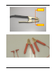
AUTO-OHM 100/200 Series 2 Operating Procedures Current Jaw Voltage Jaw Figure 1.0 Combined Current and Sense Leads Figure 2.
AUTO-OHM 100/200 Series 2 Operating Procedures Figure 3.0 Auto-Ohm 100/200 Hand Spikes Figure 4.
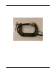
AUTO-OHM 100/200 Series 2 Operating Procedures 1.5 Optional Accessories 1. Heavy-duty welding-type C-clamps (Figure 5.0) are available as optional accessories. These C-clamps allow test lead connections to a wide variety of bushing sizes, bus bars, and conductors that require low-resistance test-lead contacts. 2. Light weight (#4 AWG) cables are also available upon request. 3. Custom cable lengths are available upon request. 4.
AUTO-OHM 100/200 Series 2 Operating Procedures 2.0 AUTO-OHM SPECIFICATIONS 2.1 Auto-Ohm 100 Series 2 Specifications Table 1.0 Auto-Ohm 100 Series 2 Specifications MODEL ...................... Auto-Ohm 100 Series 2 TYPE ............................. Special-Purpose Test Equipment, Portable, Low Resistance-Ohmmeter CONFIGURATION...... Third-generation (improved design, superseding original model) SIZE (inches) .............. 16.8 Wide by 12.6 High by 10.6 Deep (42.7 Cm x 32 Cm x 30.5 Cm) WEIGHT.............
AUTO-OHM 100/200 Series 2 Operating Procedures 2.2 Auto-Ohm 200 Series 2 Specifications Table 2.0 Auto-Ohm 200 Series 2 Specifications MODEL ...................... Auto-Ohm 200 Series 2 TYPE ............................. Special-Purpose Test Equipment, Portable, Low Resistance-Ohmmeter CONFIGURATION...... Third-generation (improved design, superseding original model) SIZE (inches) .............. 16.8 Wide by 12.6 High by 10.6 Deep (42.7 Cm x 32 Cm x 30.5 Cm) WEIGHT........................
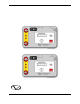
AUTO-OHM 100/200 Series 2 Operating Procedures 3.0 CONTROL AND DISPLAY 3.1 Auto-Ohm 100 Series 2 Front Panel The Auto-Ohm 100 Series 2 controls and displays are shown in the control-panel illustration below (Figure 6.0). Pointing leader lines reference each item with an index number. Each index number is cross-referenced to a functional description in Table 3.0, which describes the function and purpose of each item on the control panel.
AUTO-OHM 100/200 Series 2 Operating Procedures Table 3.0 Functional Description of Auto-Ohm 100 Series 2 Controls and Display Figure 6.0 Index # Adjacent Panel Marking 1&8 (Wing Nut) 2 100-240 Vac, 8A, 50-60 Hz 3 4 5 6 7 9 & 10 no marking GROUND (Wing Nut) RS-232C HIGH CURRENT PRESENT CHANGE “PUSH” TO SELECT (resistor symbol) Functional Description Current lead connectors Input power connector with third-wire safety ground and built-in 10A circuit breaker.
AUTO-OHM 100/200 Series 2 Operating Procedures 3.2 Auto-Ohm 200 Series 2 Front Panel The Auto-Ohm 200 Series 2 controls and displays are shown in the control-panel illustration, Figure 7.0. Pointing leader lines reference each item with an index number. Each index number is cross-referenced to a functional description in Table 4.0, which describes the function and purpose of each item on the control panel.
AUTO-OHM 100/200 Series 2 Operating Procedures Table 4.0 Functional Description of Auto-Ohm 200 Series 2 Controls and Display Figure 7.0 Index # Adjacent Panel Marking 1&8 (Wing Nut) 2 100-240 Vac, 8A, 50-60 Hz 3 4 5 6 7 9 & 10 no marking GROUND (Wing Nut) RS-232C HIGH CURRENT PRESENT CHANGE “PUSH” TO SELECT (resistor symbol) Functional Description Current lead connectors Input power connector with third-wire safety ground and built-in 10A circuit breaker.
AUTO-OHM 100/200 Series 2 Operating Procedures 4.0 OPERATING VOLTAGES The Auto-Ohm operates on voltages between 100-240Vac, 50/60Hz. 5.0 CABLE CONNECTION The Auto-Ohm is supplied with 30-foot test cables with heavy-duty alligator clamps. Both the current (#1 AWG) and sense leads are combined into one cable (Figure 1.0). A typical cable connection for the Auto-Ohm to a device under test (using the combined test leads) is shown in Figure 9.0 and Figure 11.0. Figure 8.0 and Figure 10.
AUTO-OHM 100/200 Series 2 Operating Procedures Figure 10.0 AUTO-OHM 100/200 Connection Diagram 3 (Separate Leads) Figure 11.
AUTO-OHM 100/200 Series 2 Operating Procedures Figure 12.
AUTO-OHM 100/200 Series 2 Operating Procedures 6.0 OPERATING THE AUTO-OHM The Auto-Ohm is operated with one dual-function control knob. The operator turns the control knob to scroll through different menu selections on the display. When the desired option appears, it is selected by pressing the control knob like a pushbutton. Review Figure 12.0 before proceeding with the step-by-step procedures that follow. 6.
AUTO-OHM 100/200 Series 2 Operating Procedures h. When the option of choice appears in the MAIN MENU, press (or “Push”) the control knob to enter the selection and start that sequence. The step-by-step operating procedures to follow describe each of the selected options in the order listed above. 6.4 Running a Normal Test Procedure To run a test, turn the control knob until RUN TEST appears on the display, then press the control knob to begin the procedures for running a test.
AUTO-OHM 100/200 Series 2 Operating Procedures c. Custom current is defaulted to 50 amperes for the Auto-Ohm 100 (100A for Auto-Ohm 200) in this menu. Turning the control knob clockwise or counter-clockwise will increment or decrement the current reading on the display. Turn the control knob until the desired current is displayed, then press the control knob to enter the desired current. The display will now show the BURN IN TIME menu (Figure 18.0).
AUTO-OHM 100/200 Series 2 Operating Procedures g. The display above shows the current ramp percentage of the test-level current. The Auto-Ohm will ramp the test current from 0 (zero) amperes to the selected test current level in the selected ramp time. The test current is automatically ramped up and down. This current ramp rate is programmable from 5 seconds to 30 seconds. When the current reaches 100%, the next display (shown in Figure 22.0) appears automatically.
AUTO-OHM 100/200 Series 2 Operating Procedures 6.5 Running an Automatic Test Procedure The TEST TYPE menu allows the user to select the Normal or Automatic test mode. In the Automatic test mode the user selects the test current and ramp time. The measurement cycle is initiated when the sense leads are connected to the device under test. This feature is handy when the user wants to take resistance readings of multiple points.
AUTO-OHM 100/200 Series 2 Operating Procedures b. This menu allows the user to select any test current from 10 to 100 amperes (or 200 amperes for Auto-Ohm 200) in 2 amperes steps. SET CURRENT: 50 AMPS Figure 29.0 Custom Current Menu c. Custom current is defaulted to 50AMPS for the Auto-Ohm 100 (100A for Auto-Ohm 200) in this menu. Turning the control knob clockwise or counter-clockwise will increment or decrement the current reading on the display.
AUTO-OHM 100/200 Series 2 Operating Procedures I=10 AMPS 101.0 MICRO-OHM Figure 33.0 Automatic Mode Test results g. To initiate another test, disconnect and reconnect the sense leads to the device under test. To terminate the Automatic Test Mode, press the Auto-Ohm control knob. NOTE The user should allow two seconds between disconnecting and reconnecting to the test leads to initiate a new test. 6.
AUTO-OHM 100/200 Series 2 Operating Procedures b. Turn the control knob until the contrast is suitable. Press the control knob to set the contrast. The display will return to the MAIN MENU. The contrast setting will be recalled each time the Auto-Ohm is turned on and remain until it is changed again using this procedure. 6.
AUTO-OHM 100/200 Series 2 Operating Procedures Figure 40.0 Calibration Connection (Combined Leads) c. During the calibration check the display below (Figure 41.0) shows the current ramping status. When the test current ramps to 100 %, this display is automatically replaced with the test result display of Figure 42.0 or Figure 43.0. CUR RAMP: 20% Figure 41.0 Current Ramp Message CUR RAMP ERROR! CHECK CABLES Figure 42.0 Current-Ramp Error Message d.
AUTO-OHM 100/200 Series 2 Operating Procedures the display. The Auto-Ohm will continue to beep until the control knob is pressed. Once the problem has been fixed, the CAL CHECK can be rerun. ZERO CKT CHECK “PASS” Figure 44.0 Zero Circuit Test Message f. The Auto-Ohm checks the ZERO circuit. The “PASS” message is displayed as shown above in Figure 44.0. FSCL CKT CHECK “PASS” Figure 45.0 Full-Scale Circuit Test Message g. The full scale range check (FSCL CKT CHECK) is performed next.
AUTO-OHM 100/200 Series 2 Operating Procedures 6.9 Display Previous Results The purpose of this procedure is to let an operator view the last 3 readings stored in the AutoOhm. To view previous results, turn the control knob to select the PREV RESULTS option from the MAIN MENU, as shown in Figure 48.0. MAIN MENU Figure 48.0 Previous Results Menu a. Press the control knob to select this option. The user now can select any of the last three readings to be displayed.
AUTO-OHM 100/200 Series 2 Operating Procedures APPENDIX A Auto-Ohm Troubleshooting Guide Item Symptom 1 Reading is incorrect. 2 “Cable Error” Message. Possible Problem 1. Poor connection at the test clamps. 1. No test current going through the device under test. 2. Sensing cables problem. 30 Solution 1. Check connections to ensure teeth of voltagesensing and current clamps are firmly in contact with the device under test. 1. Check current cable Connection to the device under test. 2.
AUTO-OHM 100/200 Series 2 Operating Procedures 1520 S. Hellman Ave., Ontario, CA 91761, USA Phone 909-923-9390 Fax 909-923-9391 Web site: http//www.vanguard-instruments.com Auto-Ohm 100/200 Series 2 HPN Jan 2009 Copyright 2009 by Vanguard Instruments Company, Inc.