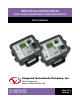
ATRT-01 S3 and ATRT-01B S3 SINGLE PHASE TRANSFORMER TURNS-RATIO METERS USER’S MANUAL Vanguard Instruments Company, Inc. 1520 S. Hellman Ave.
ATRT-01/01B S3 USER’S MANUAL REV 1 SAFETY SUMMARY This manual applies to both the ATRT-01 S3 and ATRT-01B S3 current transformer turns-ratio meters. The operating procedures are virtually the same for both models, and any differences are clearly described where applicable. FOLLOW EXACT OPERATING PROCEDURES Any deviation from procedures described in this User’s Manual may create one or more safety hazards, damage the ATRT-01/01B S3, damage the test transformer, or cause errors in the test results.
REV 1 ATRT-01/01B S3 USER’S MANUAL TABLE OF CONTENTS CONVENTIONS USED IN THIS DOCUMENT ..................................................................................... 1 1.0 INTRODUCTION .................................................................................................................... 2 1.1 General Description and Features ................................................................................... 2 1.2 Technical Specifications ...............................................
ATRT-01/01B S3 USER’S MANUAL REV 1 LIST OF TABLES Table 1. ATRT-01 S3 Technical Specifications ................................................................................. 4 Table 2. ATRT-01B S3 Technical Specifications ............................................................................... 5 Table 3. Functional Descriptions of ATRT-01 S3 Controls and Indicators ...................................... 7 Table 4. Functional Descriptions of ATRT-01B S3 Controls and Indicators ...................
REV 1 ATRT-01/01B S3 USER’S MANUAL CONVENTIONS USED IN THIS DOCUMENT This document uses the following conventions: • The general term “ATRT” is used in this manual to refer to the ATRT-01 S3 and ATRT-01B S3. • A key, switch, or knob on the ATRT is indicated as [KEY], [SWITCH], [KNOB]. • Menu names are referenced as “MENU NAME” • ATRT screen output is shown as: 1. 2. 3. 4. 5.
ATRT-01/01B S3 USER’S MANUAL 1.0 INTRODUCTION 1.1 General Description and Features REV 1 The ATRT-01 S3 is Vanguard’s fourth generation, micro-processor based, single phase, automatic transformer turns-ratio tester. This portable test unit is available in two models, the ATRT-01 S3 (line power only), and the ATRT-01B S3 (rechargeable-battery powered). The ATRT-01 S3 uses the IEEE C57.12.90 measuring method to determine the transformer turns-ratio.
REV 1 ATRT-01/01B S3 USER’S MANUAL Battery Power for Exceptional Portability The ATRT-01B S3 is powered by a 6-volt, 7 ampere-hour, lead acid battery. This high capacity battery, coupled with the ATRT-01B S3’s low power consuming circuitry, allows the unit to be used continuously for up to 4 hours per charge. A built-in charger allows the unit to be used during charging.
ATRT-01/01B S3 USER’S MANUAL 1.2 REV 1 Technical Specifications 1.2.1. ATRT-01 S3 Technical Specifications Table 1. ATRT-01 S3 Technical Specifications TYPE Transformer Turns Ratio Tester PHYSICAL SPECIFICATIONS Dimensions: 12” x 10” x 8” (30.4 cm x 25.4 cm x 20.3 cm) Weight: 8 lbs (3.6 Kg) INPUT POWER 120 or 240 Vac (Selectable), 50/60 Hz MEASURING METHOD ANSI/IEEE C57.12.90 RATIO MEASURING RANGE 0.8 - 15,000 (5 digit resolution) TURNS-RATIO ACCURACY 40 Vac: 0.8-1,999 (0.1%), 2,000-3,999 (0.
REV 1 ATRT-01/01B S3 USER’S MANUAL 1.2.2. ATRT-01B S3 Technical Specifications Table 2. ATRT-01B S3 Technical Specifications TYPE Transformer Turns Ratio Tester PHYSICAL SPECIFICATIONS Dimensions: 12” x 10” x 8” (30.4 cm x 25.4 cm x 20.3 cm) Weight: 9 lbs (4.3 Kg) INPUT POWER 90 to 240 Vac, 50/60 Hz Battery: SLA battery delivering up to 4 hours of continuous operation per charge. MEASURING METHOD ANSI/IEEE C57.12.90 RATIO MEASURING RANGE 0.8 - 15,000 (5 digit resolution) TURNS-RATIO ACCURACY 40 Vac: 0.
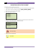
ATRT-01/01B S3 USER’S MANUAL REV 1 1.2.3. Controls and Indicators The ATRT-01 S3 and ATRT-01B S3 controls and indicators are shown in Figure 1 and Figure 2, respectively. A leader line with an index number points to each control and indicator, which is cross-referenced to a functional description in the corresponding table. The purpose of the controls and indicators may seem obvious, but users should familiarize themselves with them before using the ATRT.
REV 1 ATRT-01/01B S3 USER’S MANUAL Figure 1. ATRT-01 S3 Controls and Indicators Table 3. Functional Descriptions of ATRT-01 S3 Controls and Indicators Item Number Panel Markings 1 USB MEM USB Flash drive interface 2 RS-232C RS-232C computer interface port 3 Back-lit LCD screen (128 x 64 pixels), viewable in direct sunlight and low light levels 4 H and X lead connector (16-pin male).
ATRT-01/01B S3 USER’S MANUAL REV 1 Figure 2. ATRT-01B S3 Controls and Indicators Table 4. Functional Descriptions of ATRT-01B S3 Controls and Indicators Item Number Panel Markings 1 USB MEM USB Flash drive interface 2 RS-232C RS-232C computer interface port Functional Description 3 Back-lit LCD screen (128 x 64 pixels), viewable in bright sunlight and low light levels 4 H and X lead connector (16-pin male).
REV 1 ATRT-01/01B S3 USER’S MANUAL 2.0 PRE-TEST SETUP 2.1 ATRT-01 S3 Operating Voltage The ATRT-01 S3 can be operated from 120 Vac or 240 Vac. The power voltage can be set using the voltage selector switch on the front panel (see Figure 1, item #5) 2.2 ATRT-01B S3 Operating Power The ATRT-01B S3 is powered by a rechargeable (6 Vdc / 7 AH) sealed lead acid gel battery. The unit can operate continuously for up to 6 hours between charges. It can also be used while charging.
ATRT-01/01B S3 USER’S MANUAL 3.0 OPERATING PROCEDURES 3.1 ATRT Transformer Connection Diagrams REV 1 Figure 3.
REV 1 ATRT-01/01B S3 USER’S MANUAL Figure 4.
ATRT-01/01B S3 USER’S MANUAL REV 1 Figure 5.
REV 1 ATRT-01/01B S3 USER’S MANUAL Figure 6.
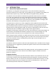
ATRT-01/01B S3 USER’S MANUAL 3.2 REV 1 Setting the Test Voltage The ATRT offers two test voltages, 4 Vac and 40 Vac. The unit always defaults to 40 Vac at power-on. The 4 Vac test voltage can be used in situations where the 40 Vac excitation voltage may saturate the CT’s. To set the test voltage: a. Turn on the unit and start from the “ START-UP” menu: 1. TEST TRANSFORMER 1. TEST TRANSFORMER 2. SETUP 3. CALCULATOR 2. SETUP 3.
REV 1 ATRT-01/01B S3 USER’S MANUAL d. The voltage will be set and the following confirmation message will be displayed: 40 VOLTS SET Press any key to return to the “START-UP” menu.
ATRT-01/01B S3 USER’S MANUAL 3.3 REV 1 Setting the Date and Time To set the date and time: a. Start from the “START-UP” menu: 1. TEST TRANSFORMER 2. SETUP 3. CALCULATOR time: date: 14:21:34 05/24/11 Press the [2] key (SETUP). b. The following screen will be displayed: 1. 2. 3. 4. RECORD ID TEST VOLTAGE PRINT RECORD SAVE/RESTORE RECORD 5. SET TIME 6. SET LANGUAGE Press the [5] key (SET TIME) c.
REV 1 3.4 ATRT-01/01B S3 USER’S MANUAL Setting the Interface Language Follow the steps below to set the interface language (English, Spanish, or Turkish): a. Start from the “START-UP” menu: 1. TEST TRANSFORMER 2. SETUP 3. CALCULATOR time: date: 14:21:34 05/24/11 Press the [2] key (SETUP). b. The following screen will be displayed: 1. 2. 3. 4. 5. RECORD ID TEST VOLTAGE PRINT RECORD SAVE/RESTORE RECORD SET TIME 6. SET LANGUAGE Press the [6] key (SET LANGUAGE). c.
ATRT-01/01B S3 USER’S MANUAL 3.5 REV 1 Setting the Frequency (ATRT-01B S3 Only) Follow the steps below to set the preferred frequency (50 or 60 Hz): a. Start from the “START-UP” menu: 1. TEST TRANSFORMER 2. SETUP 3. CALCULATOR bAT: time: date: 14:21:34 05/24/11 Press the [2] key (SETUP). b. The following screen will be displayed: 1. 2. 3. 4. 5. 6. 7. RECORD ID TEST VOLTAGE PRINT RECORD SAVE/RESTORE RECORD SET TIME SET LANGUAGE SET 50/60 HZ Press the [7] key (SET 50/60 HZ). c.
REV 1 3.6 ATRT-01/01B S3 USER’S MANUAL Performing Tests 3.6.1. Entering Test Record Header Information You can enter the test record header information before performing tests. The record header includes identifying information such as the company, station, circuit, manufacturer, etc. Once the header information has been set, it will apply to all subsequent test records. Follow the steps below to enter the test header information: a. Start from the “START-UP” menu: 1. TEST TRANSFORMER 2. SETUP 3.
ATRT-01/01B S3 USER’S MANUAL REV 1 d. The following screen will be displayed: STATION: _ ↑ /↓ TO POSITION "ENTER" TO ACCEPT Type the station name using the alpha-numeric keypad and then press the [ENTER] key. e. The following screen will be displayed: CIRCUIT: _ ↑ /↓ TO POSITION "ENTER" TO ACCEPT Type the circuit information using the alpha-numeric keypad and then press the [ENTER] key. f.
REV 1 ATRT-01/01B S3 USER’S MANUAL g. The following screen will be displayed: MODEL: _ ↑ /↓ TO POSITION "ENTER" TO ACCEPT Type the transformer’s model information using the alpha-numeric keypad and then press the [ENTER] key. h. The following screen will be displayed: SERIAL NUMBER: _ ↑ /↓ TO POSITION "ENTER" TO ACCEPT Type the transformer’s serial number using the alpha-numeric keypad and then press the [ENTER] key. i.
ATRT-01/01B S3 USER’S MANUAL j. REV 1 The following screen will be displayed: OPERATOR: _ ↑ /↓ TO POSITION "ENTER" TO ACCEPT Type the operator’s name using the alpha-numeric keypad and then press the [ENTER] key. All header information will be saved, and you will be returned to the “START-UP” menu.
REV 1 ATRT-01/01B S3 USER’S MANUAL 3.6.2. Testing a Single Phase Transformer Follow the steps below to test a single phase transformer: a. Start from the “START-UP” menu: 1. TEST TRANSFORMER 2. SETUP 3. CALCULATOR time: date: 14:21:34 05/24/11 Press the [1] key (TEST TRANSFORMER). b. The following screen will be displayed: XFMR CONFIG: 1. 2. 3. 4. 5. 6. SINGLE PHASE Dy YD DD YY NEXT PAGE Press the [1] key (SINGLE PHASE). c. The following screen will be displayed: NAME PLATE VOLTAGE? 1. yes 2. no 3.
ATRT-01/01B S3 USER’S MANUAL REV 1 NAME PLATE VOLTAGE: H : X 0 : Type the H winding name plate voltage value using the numeric keypad. The screen will be updated as shown: NAME PLATE VOLTAGE: H : X 500 : Press the [ENTER] key. The following screen will be displayed: NAME PLATE VOLTAGE: H : X 500 : 0 Type the X winding name plate voltage value using the numeric keypad. The screen will be updated as shown: NAME PLATE VOLTAGE: H : X 500 : 10 Press the [ENTER] key. Continue to step d. 2.
REV 1 ATRT-01/01B S3 USER’S MANUAL d. The following screen will be displayed: "START" TO TEST OR "STOP" TO ABORT Press the [START] key to start the test. e. The following screen will be displayed while the test is being performed: TESTING AT 40 VOLTS TEST IN PROGRESS PLEASE WAIT... The test results will be displayed on the LCD screen when testing has finished: RAT: +1.003 PHS: 0.02° mA: 0.0 ERR: 0.05% The percentage error (ERR) will be displayed only if name plate voltage values were entered.
ATRT-01/01B S3 USER’S MANUAL REV 1 f. The following screen will be displayed: KEEP THIS READING? 1. YES 2. NO Press the [1] key (YES) to save the reading. g. The following screen will be displayed: TEST SAVED Press any key to continue. NOTE The above screen will be displayed if there is currently no data in the unit’s memory buffer.
REV 1 ATRT-01/01B S3 USER’S MANUAL h. The following screen will be displayed: RUN ANOTHER TEST? 1. YES 2. NO 3. REPEAT PREV. TEST Press the [2] key (NO). i. The following screen will be displayed: SAVE THIS RECORD? 1. YES 2. NO Press the [1] key (YES) to save the test record to the unit’s Flash EEPROM. j.
ATRT-01/01B S3 USER’S MANUAL REV 1 3.6.3. Testing a Three Phase Transformer Follow the steps below to test a three phase transformer: a. Start from the “START-UP” menu: 1. TEST TRANSFORMER 2. SETUP 3. CALCULATOR time: date: 14:21:34 05/24/11 Press the [1] key (TEST TRANSFORMER). b. The following screen will be displayed: XFMR CONFIG: 1. SINGLE PHASE 2. 3. 4. 5. 6. Dy YD DD YY NEXT PAGE You can press the [6] key (NEXT PAGE) to view additional transformer types.
REV 1 ATRT-01/01B S3 USER’S MANUAL d. The following screen will be displayed: 1. 2. 3. 4. 5. 6. DY1 DY3 DY5 DY7 DY9 DY11 Select the transformer configuration by pressing the corresponding key ([1] to [6]). For this example, press the [1] key (Dy1). e. The following screen will be displayed: NAME PLATE VOLTAGE? 1. yes 2. no 3. USE PREV DATA Option 3 (USE PREV DATA) will be listed only if you had provided name plate voltages for a previous test. NOTE 1.
ATRT-01/01B S3 USER’S MANUAL REV 1 NAME PLATE VOLTAGE: H : X 500 : 0 Type the X winding name plate voltage value using the numeric keypad. The screen will be updated as shown: NAME PLATE VOLTAGE: H : X 500 : 10 Press the [ENTER] key. Continue to step f. 2. NO Press the [2] key (NO) if you do not want to enter the transformer name plate voltage. Continue to step f. 3. USE PREV DATA Press the [3] key (USE PREV DATA) to use the name plate voltage values entered when performing the last test.
REV 1 ATRT-01/01B S3 USER’S MANUAL Make the cable connections per the instructions and then press the [START] key to run the Phase A test. g. The following screen will be displayed while the test is being performed: TESTING: DYN1 phase a The Phase A test results will be displayed on the LCD screen when testing has finished: RATIO +15.003 MA 001 %DIFF 0.02 "ENTER" TO CONTINUE.. Press the [ENTER] key to continue. h.
ATRT-01/01B S3 USER’S MANUAL RATIO +15.003 +15.015 REV 1 %DIFF MA 001 001 0.02 0.10 "ENTER" TO CONTINUE.. Line 1 of the results shows the Phase A test results, and line 2 shows the Phase B test results. Press the [ENTER] key to continue. j.
REV 1 l. ATRT-01/01B S3 USER’S MANUAL The following screen will be displayed: KEEP THIS READING? 1. YES 2. NO Press the [1] key (YES) to save the reading. m. The following screen will be displayed: TEST SAVED Press any key to continue. NOTE The above screen will be displayed if there is currently no data in the unit’s memory buffer.
ATRT-01/01B S3 USER’S MANUAL REV 1 n. The following screen will be displayed: RUN ANOTHER TEST? 1. YES 2. NO 3. REPEAT PREV. TEST Press the [2] key (NO). o. The following screen will be displayed: SAVE THIS RECORD? 1. YES 2. NO Press the [1] key (YES) to save the test record to the unit’s Flash EEPROM. p.
REV 1 3.7 ATRT-01/01B S3 USER’S MANUAL Working With Test Records 3.7.1. Viewing the Contents of the Working Memory Whenever a test is performed or a test record is retrieved, the data is stored in the ATRT’s working memory. You can view the test data using the steps below: a. Start from the “START-UP” menu: 1. TEST TRANSFORMER 2. SETUP 3. CALCULATOR time: date: 14:21:34 05/24/11 Press the [2] key (SETUP). b. The following screen will be displayed: 1. RECORD ID 2. TEST VOLTAGE 3. 4. 5. 6.
ATRT-01/01B S3 USER’S MANUAL REV 1 3.7.2. Saving Test Results to a Test Record After performing a test, the user is presented the option to save the test results to the unit’s Flash EEPROM or to a USB Flash Drive. If the test results are not saved immediately after performing a test, they will still remain in the working memory and can be saved later, as long as a new test has not been performed and the unit has not been turned off.
REV 1 ATRT-01/01B S3 USER’S MANUAL If a USB Flash drive is connected to the unit, continue to step d. If a USB Flash drive is NOT connected to the unit, continue to step e. d. The following screen will be displayed: 1. SAVE INTERNALLY 2. SAVE TO THUMB DRIVE 1. SAVE INTERNALLY Press the [1] key (SAVE INTERNALLY) to save the test record to the unit’s Flash EEPROM. Continue to step e. 2. SAVE TO THUMB DRIVE Press the [2] key (SAVE TO THUMB DRIVE) to save the test record to the connected USB Flash drive.
ATRT-01/01B S3 USER’S MANUAL REV 1 3.7.3. Restoring a Test Record From Flash EEPROM Use the steps below to restore a test record from the ATRT’s Flash EEPROM to the working memory: a. Start from the “START-UP” menu: 1. TEST TRANSFORMER 2. SETUP 3. CALCULATOR time: date: 14:21:34 05/24/11 Press the [2] key (SETUP). b. The following screen will be displayed: 1. RECORD ID 2. TEST VOLTAGE 3. PRINT RECORD 4. SAVE/RESTORE RECORD 5. SET TIME 6. SET LANGUAGE Press the [4] key (SAVE/RESTORE RECORD). c.
REV 1 ATRT-01/01B S3 USER’S MANUAL d. The following screen will be displayed: RESTORE RECORD 1.ENTER RECORD NUMBER 2.SCROLL TO SELECT If you have a USB Flash drive inserted in the ATRT’s “USB MEM” port, the following screen will be displayed instead of the above screen: NOTE 1.INTERNAL STORAGE 2.THUMB DRIVE Press the [1] key (INTERNAL STORAGE). The following screen will be displayed: RESTORE RECORD 1.ENTER RECORD NUMBER 2.SCROLL TO SELECT Continue with the steps below. 1.
ATRT-01/01B S3 USER’S MANUAL 1.2. REV 1 The following screen will be displayed: RECORD RESTORED! DISPLAY RECORD? 1.YES 2.NO Press the [1] key (YES) to display the test record. 1.3. The basic information about the restored test record will be displayed as shown: SINGLE PHASE Num Tests: 1 05/27/11 15:25:57 Press the [Contrast ∨] key. The test record details will be displayed as shown: 1 SINGLE PHASE 40 volts RATIO ma %DIFF 1.003 0002 0.3 Press the [STOP] key to return to the “START-UP” menu.
REV 1 ATRT-01/01B S3 USER’S MANUAL Press the [Contrast ∧] button or the [Contrast ∨] key to display the next or previous test record, respectively. The basic test record information will be displayed as shown: #1 05/25/11 09:52 SINGLE PHASE 1 TESTS When you have located the test record that you would like to restored, press the [ENTER] key. Continue to step 1.2 on page 40.
ATRT-01/01B S3 USER’S MANUAL REV 1 3.7.4. Restoring a Test Record From a USB Flash Drive Use the steps below to restore a test record from a USB Flash drive to the ATRT’s working memory: a. Make sure the USB Flash drive containing the test record(s) is inserted in the ATRT’s USB Flash drive port (“USB MEM” port). Then start from the “START-UP” menu: 1. TEST TRANSFORMER 2. SETUP 3. CALCULATOR time: date: 14:21:34 05/24/11 Press the [2] key (SETUP). b. The following screen will be displayed: 1.
REV 1 ATRT-01/01B S3 USER’S MANUAL d. The following screen will be displayed: 1.INTERNAL STORAGE 2.THUMB DRIVE Press the [2] key (THUMB DRIVE). e. The following screen will be displayed: RESTORE THUMB DRIVE REC_ Type the record number that you would like to restore using the alpha-numeric keypad and then press the [ENTER] key. f. The test record will be restored to the unit’s working memory and the following screen will be displayed: REC_000 restored! DISPLAY RECORD? 1.YES 2.
ATRT-01/01B S3 USER’S MANUAL REV 1 Press the [Contrast ∨] key. The test record details will be displayed as shown below: 1 SINGLE PHASE 40 volts RATIO ma %DIFF 1.003 0002 0.3 Press the [STOP] key to return to the “START-UP” menu. The restored test record will remain loaded in the working memory.
REV 1 ATRT-01/01B S3 USER’S MANUAL 3.7.5. Copying Test Records to a USB Flash Drive Use the steps below to copy one or all test records from the unit’s Flash EEPROM to a connected USB Flash drive: a. Make sure a USB Flash drive is connected to the unit’s “USB MEM” port, and then start from the “START-UP” menu: 1. TEST TRANSFORMER 2. SETUP 3. CALCULATOR time: date: 14:21:34 05/24/11 Press the [2] key (SETUP). b. The following screen will be displayed: 1. RECORD ID 2. TEST VOLTAGE 3. PRINT RECORD 4.
ATRT-01/01B S3 USER’S MANUAL REV 1 d. The following screen will be displayed: COPY REC TO THUMB DRV 1.COPY SINGLE RECORD 2.COPY ALL RECORDS 1. COPY SINGLE RECORD Press the [1] key (COPY SINGLE RECORD) to copy a single test record from the ATRT’s Flash EEPROM to the connected USB Flash drive. The following screen will be displayed: ENTER RECORD NUMBER TO COPY TO FLASH DRV NUMBER: Type the record number using the alpha-numeric keypad and then press the [ENTER] key.
REV 1 ATRT-01/01B S3 USER’S MANUAL 2. COPY ALL RECORDS Press the [2] key (COPY ALL RECORDS) to copy all test records from the ATRT’s Flash EEPROM to the connected USB Flash drive. All test records will be copied from the unit to the connected USB Flash drive. The following screen will be displayed when the process is finished: ALL RECORDS HAVE BEEN TRANSFERRED TO THUMB DRIVE! Press any key to return to the “START-UP” menu.
ATRT-01/01B S3 USER’S MANUAL REV 1 3.7.6. Viewing the Test Record Directory Use the steps below to browse through a directory of the test records stored in the ATRT’s Flash EEPROM memory: a. Start from the “START-UP” menu: 1. TEST TRANSFORMER 2. SETUP 3. CALCULATOR time: date: 14:21:34 05/24/11 Press the [2] key (SETUP). b. The following screen will be displayed: 1. RECORD ID 2. TEST VOLTAGE 3. PRINT RECORD 4. SAVE/RESTORE RECORD 5. SET TIME 6. SET LANGUAGE Press the [4] key (SAVE/RESTORE RECORD). c.
REV 1 ATRT-01/01B S3 USER’S MANUAL d. The following screen will be displayed: RECORDS DIRECTORY "UP" TO SCROLL FWD "DWN" TO SCROLL RVS Press the [Contrast ∧] or [Contrast ∨] key to scroll through the test record directory. The test record header will be displayed as shown: SINGLE PHASE Num Tests: 1 05/27/11 15:25:57 You can continue to scroll through the record directory by pressing the [Contrast ∧] and [Contrast ∨] keys. Press the [STOP] key to return to the “START-UP” menu.
ATRT-01/01B S3 USER’S MANUAL REV 1 3.7.7. Erasing Test Records from the Flash EEPROM Follow the steps below to erase test records from the Flash EEPROM a. Start from the “START-UP” menu: 1. TEST TRANSFORMER 2. SETUP 3. CALCULATOR time: date: 14:21:34 05/24/11 Press the [2] key (SETUP). b. The following screen will be displayed: 1. RECORD ID 2. TEST VOLTAGE 3. PRINT RECORD 4. SAVE/RESTORE RECORD 5. SET TIME 6. SET LANGUAGE Press the [4] key (SAVE/RESTORE RECORD). c.
REV 1 ATRT-01/01B S3 USER’S MANUAL d. The following screen will be displayed: ERASE RECORD 1.ERASE SINGLE REC. 2.ERASE ALL RECORDS "STOP" TO EXIT If you have a USB Flash drive inserted in the ATRT’s “USB MEM” port, the following screen will be displayed instead of the above screen: NOTE 1.ERASE INTERNAL REC 2.ERASE THUMB DRV REC Press the [1] key (ERASE INTERNAL REC). The following screen will be displayed: ERASE RECORD 1.ERASE SINGLE REC. 2.
ATRT-01/01B S3 USER’S MANUAL REV 1 ERASE RECORD NUMBER: You can cancel the process and return to the “START-UP” menu by pressing the [STOP] key. NOTE Type the record number that you would like to erase using the alpha-numeric keypad and then press the [ENTER] key. If you do not know the test record number, you can first view the test record directory using the instructions in section 3.7.6. The following screen will be displayed while the record is being erased: ERASing record PLEASE WAIT...
REV 1 ATRT-01/01B S3 USER’S MANUAL 2. SCROLL TO SELECT Press the [2] key (SCROLL TO SELECT) to scroll through the test record directory and locate the test record that you would like to erase. The following screen will be displayed: RECORDS DIRECTORY "UP" TO SCROLL FWD "DWN" TO SCROLL RVS Press the [Contrast ∧] or [Contrast ∨] key to scroll through the test record directory.
ATRT-01/01B S3 USER’S MANUAL REV 1 2. ERASE ALL RECORDS Press the [2] key (ERASE ALL RECORDS) to erase all the test records from the unit’s internal Flash EEPROM. The following warning screen will be displayed: ERASE ALL RECORDS! ARE YOU SURE? "ENTER" To CONTINUE. You can press the [STOP] key to cancel the process and return to the “START-UP” menu. Press the [ENTER] key to proceed with deleting all the test records from the unit’s Flash EEPROM.
REV 1 ATRT-01/01B S3 USER’S MANUAL 3.7.8. Erasing Test Records from a USB Flash Drive Follow the steps below to erase test records from a USB Flash drive: a. Make sure a USB Flash drive is connected to the unit’s “USB MEM” port, and then start from the “START-UP” menu: 1. TEST TRANSFORMER 2. SETUP 3. CALCULATOR time: date: 14:21:34 05/24/11 Press the [2] key (SETUP). b. The following screen will be displayed: 1. RECORD ID 2. TEST VOLTAGE 3. PRINT RECORD 4. SAVE/RESTORE RECORD 5. SET TIME 6.
ATRT-01/01B S3 USER’S MANUAL REV 1 e. The following screen will be displayed: ERASE RECORD 1.ERASE SINGLE REC. 2.ERASE ALL RECORDS "STOP" TO EXIT 1. ERASE SINGLE REC. Press the [1] key (ERASE SINGLE REC.) to erase a single test record from the connected USB Flash drive. The following screen will be displayed: ERASE THUMB DRIVE REC_ Type the record number that you would like to erase using the alpha-numeric keypad and then press the [ENTER] key.
REV 1 ATRT-01/01B S3 USER’S MANUAL Press the [STOP] key if you do not want to erase all the test records. You will be returned to the “START-UP” menu. Press the [ENTER] key to proceed with deleting all the test records from the connected USB Flash drive. The following screen will be displayed when all the records have been erased: all thumb drive records erased! Press any key to return to the “START-UP” menu.
ATRT-01/01B S3 USER’S MANUAL 3.8 REV 1 Using the Turns Ratio Calculator The ATRT-01 and ATRT-01B S2 feature a turns ratio calculator that can be used to calculate the turns ratio for various transformer types. The user only needs to provide the H and X name plate voltage values and the unit will calculate the turns ratio. Follow the steps below to use the turns ratio calculator. a. Start from the “START-UP” menu: 1. TEST TRANSFORMER 2. SETUP 3.
REV 1 ATRT-01/01B S3 USER’S MANUAL c. The following screen will be displayed: H0 accessible? 1. YES 2. NO 1. YES Press the [1] key (YES) if H0 is accessible. The following screen will be displayed: 1. 2. 3. 4. 5. 6. YND1 YND3 YND5 YND7 YND9 YND11 Select the transformer configuration by pressing the corresponding key. Continue to step d. 2. NO Press the [2] key (NO) if H0 is not accessible. The following screen will be displayed: 1. 2. 3. 4. 5. 6.
ATRT-01/01B S3 USER’S MANUAL REV 1 d. The following screen will be displayed NAME PLATE VOLTAGE: H : X 0 : Type the H name plate voltage value using the keypad. The screen will be updated: NAME PLATE VOLTAGE: H : X 1,734 : Press the [ENTER] key. The following screen will be displayed: NAME PLATE VOLTAGE: H : X 1,734 : 0 Type the X name plate voltage using the keypad. The screen will be updated: NAME PLATE VOLTAGE: H : X 1,734 : 100 Press the [ENTER] key.
REV 1 ATRT-01/01B S3 USER’S MANUAL APPENDIX A – TRANSFORMER VECTOR GROUP CODES Utility power transformers manufactured in accordance with IEC specifications have a Rating Plate attached in a visible location. This plate contains a list of the transformer's configuration and operating specifications. One such rating is the winding configuration and phasedisplacement code. This code follows a convention that comprises letter and number sets that denote three-phase winding configurations (i.e.
ATRT-01/01B S3 USER’S MANUAL REV 1 APPENDIX B – Common ANSI Transformer Descriptions 62
REV 1 63 ATRT-01/01B S3 USER’S MANUAL
ATRT-01/01B S3 USER’S MANUAL REV 1 64
REV 1 65 ATRT-01/01B S3 USER’S MANUAL
ATRT-01/01B S3 USER’S MANUAL REV 1 66
REV 1 67 ATRT-01/01B S3 USER’S MANUAL
ATRT-01/01B S3 USER’S MANUAL REV 1 68
REV 1 69 ATRT-01/01B S3 USER’S MANUAL
ATRT-01/01B S3 USER’S MANUAL REV 1 APPENDIX C – CEI/IEC 60076-1 Transformer Descriptions 70
REV 1 71 ATRT-01/01B S3 USER’S MANUAL
ATRT-01/01B S3 USER’S MANUAL REV 1 72
REV 1 73 ATRT-01/01B S3 USER’S MANUAL
ATRT-01/01B S3 USER’S MANUAL REV 1 74
REV 1 75 ATRT-01/01B S3 USER’S MANUAL
ATRT-01/01B S3 USER’S MANUAL REV 1 76
REV 1 ATRT-01/01B S3 USER’S MANUAL APPENDIX D – Australian Std.
ATRT-01/01B S3 USER’S MANUAL REV 1 78
REV 1 79 ATRT-01/01B S3 USER’S MANUAL
ATRT-01/01B S3 USER’S MANUAL REV 1 80
REV 1 81 ATRT-01/01B S3 USER’S MANUAL
ATRT-01/01B S3 USER’S MANUAL REV 1 82
REV 1 83 ATRT-01/01B S3 USER’S MANUAL
1520 S. Hellman Ave • Ontario, CA 91761 • USA Phone: 909-923-9390 • Fax: 909-923-9391 www.vanguard-instruments.com Copyright © 2011 by Vanguard Instruments Company, Inc. ATRT-01/01B S3 User’s Manual • Revision 1.