
User guide

Model ATRT-01 (v) Operating Instructions
Rev 02
May 02, 2002
5
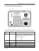
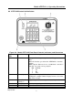
4.0 Principle of Operation
The ATRT-01 measures transformer turns ratio by applying a test voltage across the (H) winding
and sensing induced voltage on the secondary (X) winding. (For safety, testing is always done in a
step-down transfer, regardless of the transformer’s actual use.) There's no load on windings during
testing, so measured voltage ratio is virtually the same as the winding turns ratio. The ATRT-01
measures turns ratios in a range from 0.8 to 15,000. Excitation current (via H leads) is measured
for reference and ranges from 0.0 to 2,000 mA (0 to 200 milliamperes for ATRT-01B and ATRT-
01D). Winding polarity is displayed as "+" (in phase) or "-" (out of phase). The ATRT-01
calibrates its own sensing circuits before each test; therefore, calibration by the operator is not
required.
5.0 Specifications
Model ATRT-01(v) specifications are listed below in Table 5-1
Table 5-1. Model ATRT-01 (v) Turns-Ratio Meter Specifications
(Unless otherwise indicated, each specification is the same for all three ATRT-01 models.)
Type Portable, Automatic, Single-Phase Transformer Turns-Ratio Meter
Size (inches) 12 L by 8 W by 9 H
Weight (pounds) ATRT-01: 8, ATRT-01B: 9.5, ATRT-01D: 9.5
Turns Ratio-Measuring Ranges 0.800 to 15,000.00
Turns-Ratio Accuracy 0.8-999: ?0.1 %
1,000-1,499: ?0.2 %
1,500-1,999: ?1.0 %
2,000-15,000: ?2.0%
Calibration Self Calibrating; No operator calibration required
Excitation Voltage ATRT-01: 40 Volts ac, ATRT-01B/ATRT-01D: 20 Volts ac
Excitation Current ATRT-01: 2 amps, ATRT-01B/ATRT-01D: 0 to 200 milliamperes
Current Accuracy ? 2 % of Reading (? 1 Digit)
Winding Polarity Displayed on LCD screen
Display LCD: 20 Characters wide by 4 Lines, viewable in bright sunlight
Serial Interface RS-232C, 19200 baud, 8 data bits, 2 start bits, 1 stop bit
Temperature ? Operating: -20 ?C to 55 ?C ? Storage: -40 ?C to 65 ?C
Warranty One-Year on Parts and Labor