
Datasheet


For groove mounting. Installs easily by pressing into position.
Recommended mounting groove width should be 10% less than the
O.D. dimension for mechanical press fit.
tube
.125
.125
.156
.187
.201
.219
.250
.312
.375
.438
.438
.500
.625
3,18
3,18
3,96
4,75
5,11
5,56
6,35
7,92
9,53
11,10
11,10
12,70
15,90
.062
.078
.093
.109
.125
.141
.172
.219
.266
.313
.252
.359
.484
1,57
1,98
2,36
2,77
3,18
3,58
4,37
5,56
6,76
7,95
6,40
9,12
12,30
PART NUMBER*
O
.D. I.D.
2250
2251
2300
2350
2375
2400
2450
2500
2550
2600
2610
2650
2700
O.D. I.D.
Conductive
Surface
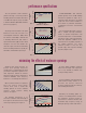
Allows the lowest compression force while maintaining excellent
electrical contact with mating surfaces. Groove mounting or pressure
sensitive adhesive. Available only in straight lengths.
angle-fold
The dart segment press-fits into a slot allowing the tubular shaped
contact bulb to incur heavy side-loads when contact with mating
surfaces is in a shear direction.
To determine correct slot dimension
for mounting, add .006”-.012” (
0,15-0,30 mm) to W
1
dimension.
tube dart
Conductive
Surface
W
2
W
1
H
1
H
2
T
R
.020
.032
.035
.045
.035
0,51
0,81
0,89
1,14
0,89
.177
.234
.350
.500
.500
4,50
5,94
8,89
12,70
12,70
.141
.142
.172
.224
.234
3,58
3,61
4,37
5,69
5,94
.059
.062
.071
.081
.093
1,50
1,57
1,80
2,06
2,36
.059
.088
.138
.210
.219
1,50
2,23
3,50
5,33
5,56
.031
.040
.043
.055
.062
.080
0,79
0,98
1,09
1,40
1,58
2,03
.250
.250
.312
.344
.437
.625
6,35
6,35
7,92
8,74
11,10
15,88
.125
.188
.250
.312
.406
.650
3,18
4,78
6,35
7,92
10,30
16,51
*
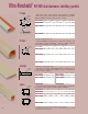
For ordering options, add the suffix nomenclature shown on page15.
Recommended compression range is 10%-30% of relaxed height and no more than 50%.
All dimensions in inches
millimeters
D-shape dart
The dart segment press-fits into a slot. This allows the D-SHAPE
contact bulb to incur heavy side-loads when contact with a mating
surface is in a shear direction while maximizing the contact area. To
determine the correct slot dimensions for mounting add .006” - .012”
(0,15-0,30 mm) to W
1
dimension.
H
D
S
T
Conductive
Surface
W
2
W
1
H
1
H
2
S
T
Conductive
Surface
W
2
W
1
W
3
W
3
.125
.312
.406
3,18
7,92
10,30
.024
.032
.036
0,61
0,81
0,91
.250
.500
.625
6,35
12,70
15,90
.141
.203
.236
3,58
5,16
5,99
.059
.078
.083
1,50
1,98
2,11
.250
.500
.625
6,35
12,70
15,90
.062
.078
.083
1,57
1,98
2,11
PART NUMBER*
H
1
H
2
W
1
W
2
W
3
TS
3125
3312
3406
.236
.308
.437
.590
.625
5,99
7,82
11,10
14,94
15,90
P
ART NUMBER*
H
1
H
2
W
1
W
2
R
T
1020
1050
1100
1200
1250
PART NUMBER*
H
WT
4125
4188
4250
4312
4406
4630
5
n/a
.020
n/a
.022
.016
.020
.025
.028
.044
.028
.039
.039
.044
.040
n/a
0,51
n/a
0,56
0,41
0,51
0,64
0,71
1,12
0,71
0,99
1,00
1,12
1,01
.030
.040
.040
.045
.053
.053
.062
.071
.073
.078
.090
.098
.103
.110
P
ART NUMBER*
O
.D. I.D.
2050
2100
2110 - NH
2125
2130
2140
2150
2155
2157
2170
2185
2200
2210
2220
0,76
1,02
1,02
1,14
1,35
1,35
1,57
1,80
1,85
1,98
2,29
2,49
2,62
2,80
PART NUMBER*
H
DSTW
1
W
2
W
3
3020
3060
.235 5,97
.328 8,33
.065 1,65
.078 1,98
.053 1,35
.062 1,58
.143 3,63
.093 2,36
.270 6,90
.093 2,36
.500 12,7
.625 15,9
.323 8,20
.500 12,70
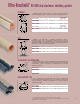
Ultra-Vanshield
®
RFI/EMI dual elastomer shielding gaskets
H
W
T
Conductive
Surface
Adhesive
Tape
Optional Clip. See Ultra-Vanshield
Clip on Page 7 for dimensions