
Operating instructions


CBPS-300 OPERATING INSTRUCTIONS
7
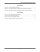
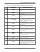
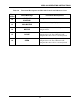
Table 2.0 Functional Descriptions of the CBPS-300 Controls and Indicators
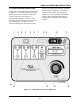
Fig. 1
Index
Panel Markings Functional Descriptions
1NONE
OPEN coil voltage positive terminal. Female,
Red connector jacks used for connecting voltage
test leads.
2
NONE
OPEN coil voltage negative terminal. Female,
Black connector jacks used for connecting
voltage test leads.
3NONE
CLOSE coil voltage positive terminal. Female,
Red connector jacks used for connecting voltage
test leads.
4 EXT TRIGGER
External trigger input for remote control. This
input is to be used with the Vanguard
Instruments Company circuit breaker timers.
Female, 4 pin connector.
5NONE
CLOSE coil voltage negative terminal. Female,
Black connector jacks used for connecting
voltage test leads.
6NONE
MOTOR voltage positive terminal. Female, Red
connector jacks used for connecting voltage test
leads.
7NONE
MOTOR coil voltage negative terminal. Female,
Black connector jacks used for connecting
voltage test leads.
8 FAULT
RESET
Fault LED. Led is lit when over current is
detected.
RESET switch. Reset fault condition and ready
CBPS-300 for next operation.
9NONE
LCD; 2-line by 16-character; back-lighted;
Displays coil/motor voltages.
10
120/240 Vac, 8A, 50- 60 Hz
Input power connector with third-wire safety
ground and 10A built-in circuit breaker
11 NONE
Safety Ground. A 5/16 threaded stud with hand-
turned wing nut. This must be connected to the
station ground before connecting any CBPS-300
test leads to the transformer.