OPERATING INSTRUCTIONS for the CBPS-300™ CIRCUIT BREAKER DC POWER SUPPLY Vanguard Instruments Company 1710 Grevillea Court Ontario, California 91761 TEL: (909) 923-9390 FAX: (909) 923-9391 April 2003 Rev 1
CBPS-300 OPERATING INSTRUCTIONS SAFETY WARNINGS AND CAUTIONS Only trained operators shall use this device. All circuit breakers under test shall be off line and fully isolated. Do Not Service or Test Alone Do not perform test procedures or service unless another person is also present who is capable of rendering aid and resuscitation.
CBPS-300 OPERATING INSTRUCTIONS Table of Contents 1.0 INTRODUCTION...................................................................................................... 4 1.1 GENERAL DESCRIPTION ........................................................................................... 4 1.2 FUNCTIONAL DESCRIPTION ...................................................................................... 4 1.3 FURNISHED ACCESSORIES ................................................................................
CBPS-300 OPERATING INSTRUCTIONS List of Tables Table 1.0 CBPS-300 SPECIFICATIONS....................................................................... 5 Table 2.0 Functional Descriptions of the CBPS-300 Controls and Indicators................ 7 Table 2.0 Functional Descriptions of CBPS-300 Controls and Indicators Cont. ............ 8 List of Figures Figure 1.0 CBPS-300 Controls and Indicators................................................................ 6 Figure 2.0 90 to 130Vac Switch Setting.........
CBPS-300 OPERATING INSTRUCTIONS 1.0 INTRODUCTION 1.1 General Description Vanguard Instruments Company produces the CBPS-300 as a microprocessorcontrolled circuit breaker DC power supply. This device was designed to replace the substation batteries during circuit breaker testing. The CBPS provides a ripple free, DC power source to operate utility circuit breakers for contact-timing and other breaker operations.
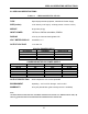
CBPS-300 OPERATING INSTRUCTIONS 2.0 CBPS-300 SPECIFICATIONS Table 1.0 CBPS-300 SPECIFICATIONS TYPE Special-purpose test equipment, Variable DC Power Supply SIZE (inches) 16.8” wide by 12.6” high by 12”deep (42.
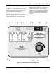
CBPS-300 OPERATING INSTRUCTIONS 3.0 CONTROLS AND INDICATORS CBPS-300 controls and indicators are shown in Figure 1.0. The leader line with an index number points to each control or indicator, which is then cross-referenced to a functional description in Table 2.0. The table describes the function of each item on the control-panel. The purpose of the controls and indicators may seem obvious, Figure 1.0 but users should become familiar with them before using the CBPS-300.
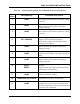
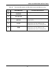
CBPS-300 OPERATING INSTRUCTIONS Table 2.0 Fig. 1 Index Functional Descriptions of the CBPS-300 Controls and Indicators Panel Markings Functional Descriptions 1 NONE OPEN coil voltage positive terminal. Female, Red connector jacks used for connecting voltage test leads. 2 NONE 3 NONE 4 EXT TRIGGER 5 NONE 6 NONE MOTOR voltage positive terminal. Female, Red connector jacks used for connecting voltage test leads. 7 NONE MOTOR coil voltage negative terminal.
CBPS-300 OPERATING INSTRUCTIONS Table 2.0 Functional Descriptions of CBPS-300 Controls and Indicators Cont. Fig. 1 Index Panel Markings 12 VOLTAGE CONTROL 13 COIL/MOTOR 14 MOTOR Functional Descriptions Voltage control knob. Coil or Motor voltage display selection. 15 16 Motor voltage initiate switch. Depress switch to energize motor. CLOSE Close coil initiate switch. Depress switch to energize close coil. The CBPS-300 will energized the close coil for 1 second period.
CBPS-300 OPERATING INSTRUCTIONS 4.0 PRETEST SETUP 4.1 Operating Voltages The operating voltages for the CBPS-300 are selectable between 90-130 Volts AC, 50/60 Hertz or 200-240 Volts AC, 50/60 Hertz. Voltage selection is set by the 120/240 selector switch as how in Figures 2.0 and Figure 3.0. Figure 2.0 90 to 130Vac Switch Setting Figure 3.
CBPS-300 OPERATING INSTRUCTIONS 5.0 OPERATING PROCEDURES Before using the CBPS-300, operators should familiarize themselves with the CBPS-300 controls and indicators. Figure 4.0 5.1 CBPS-300 Cable connection A typical connection diagram of the CBPS300 is shown in Figure 3.0. Typical CBPS-300 Connection Diagram .
CBPS-300 OPERATING INSTRUCTIONS 5.2 General Procedures a. Ground the CBPS-300 to the substation ground. (Item 11 in Figure 1.0.) 300. Failure to follow this procedure may damage the CBPS-300. 5.3 Test OPEN Coil Procedure The following procedures will allow the operator to initiate an Open operation. b. Disconnect Circuit breaker control circuitry from the substation battery. a. Make sure the CBPS-300 display voltage is selected to display coil voltage. Press Coil/Motor switch to display coil voltage.
CBPS-300 OPERATING INSTRUCTIONS b. Turn the voltage control knob to select the desired test voltage. Observe test voltage displayed on the LCD as shown below: b. Turn the voltage control knob to select the desired test voltage. Observe test voltage displayed on the LCD as shown below: MOTOR VLTG: 120.0 V COIL VLTG: 120.0 V NOTE Allow 3 seconds after setting voltage control knob for the voltage display to be stable.
CBPS-300 OPERATING INSTRUCTIONS c. Turn on the CBPS-300. d. Turn the voltage control knob to select the desired test voltage. Observe test voltage displayed on the LCD as shown below: COIL VLTG: 120.0 V NOTE Allow 3 seconds after turning voltage control knob for the voltage display to be stable. e. Initiate Open or Close command from the circuit breaker timer. f. Observe circuit breaker operated. g. To end test, turn the voltage control knob to zero position before turning off CBPS300.
CBPS-300 OPERATING INSTRUCTIONS 1710 Grevillea Court, Ontario, CA 91761, USA Phone: 909-923-9390 Fax: 909-923-9391 Website: http//www.vanguard-instruments.