
User Manual

3
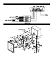
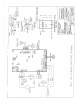
3. Connect power to terminals HOT+ and NEUT- and ground to terminal GND of TB1 as shown on
drawing.
4. Connect Sensor Cable to terminals A and B of TB1.
5. Recorder output signal is on TB3. Terminal 1 of TB3 is 0-5V output , Terminal 3 is
4-20mA output and Terminal 2 is signal ground.
Wiring Summary
Terminal No.TB1 Labeled Function
1 HOT+ Line Hot (or positive if 24V version board)
2 NEUT- Line Neutral (or negative if 24V version board)
3 GND Power and signal ground
4 NC1 Normally closed for relay #1
5 COM1 Common for relay #1
6 NO1 Normally open for relay #1
7 NC2 Normally closed for relay #2 (applies only to 6392N2)
8 COM2 Common for relay #2 (applies only to 6392N2)
9 NO2 Normally open for relay #2 (applies only to 6392N2)
10 A Sensor lead
11 B Sensor lead
12 GND Power and signal ground
13 C (not used)
14 D (not used)
Terminal No. TB2
Function
1 Aux alarm +12VDC source
2 Aux alarm open collector output relay #1
3 Aux alarm +12VDC source (applies only to 6392N2)
4 Aux alarm open collector output relay #2 (applies only to 6392N2)
Terminal No. TB3
Function
1 Recorder output 0-5VDC
2 Power and signal ground
3 Recorder output 4-20mA
4 Aux no alarm +12VDC source
5 Aux no alarm open collector output relay #1
6 Aux no alarm +12VDC source (applies only to 6392N2)
7 Aux no alarm open collector output relay #2 (applies only to 6392N2)