
Instruction manual

PREPARE THE MODEL FOR FLIGHT
Check the Control Surface Movements
❍ 1. Turn on the transmitter and receiver and center the
trims on the transmitter. If necessary, remove the servo
arms from the servos and reposition them so they are
centered. Reinstall the screws that hold on the servo arms.
❍ 2. With the transmitter and receiver still on, check all the
control surfaces to see if they are centered. Use a straight
edge to help get them set correctly. If necessary, adjust the
clevises on the pushrods to center the control surfaces.
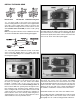
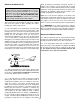
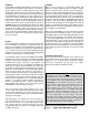
❍ 3. Make certain that the control surfaces and the
carburetor respond in the correct direction as shown in the
diagram above. If any of the controls respond in the wrong
direction, use the servo reversing switches in the
transmitter to reverse the servos connected to those
controls. Be certain the control surfaces have remained
centered. Re-adjust if necessary.
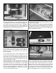
For added safety and convenience, the throttle should be
set up so that the engine can be stopped using the throttle
trim. To do this remove the clevis from the carburetor arm
and move the throttle pushrod so that the carburetor is
completely closed with the throttle stick and trim lever on
the transmitter fully back. Next, adjust the clevis so that
when the clevis is connected the carburetor barrel is in the
fully closed position. Then test the trim lever by advancing
it to full. This will be a fast idle position with the carburetor
barrel open slightly [about 1/32” or .8mm].
Now move the throttle stick forward to full. Make sure that
the carburetor barrel opens all the way. If it doesn’t open
far enough or opens too far [bending the rod] move the
pushrod and screw lock pushrod connector in or out on
the servo arm and/or the clevis on the carburetor arm to
gain or reduce movement. The throw will be correct when
the carburetor barrel will stop fully open at the same time
the throttle stick reaches full. With the throttle set up
properly, you should be able to run the engine with the trim
lever set midway to the full position [adjusted for a smooth
but slow idle]. Then when it is time to stop the engine,
simply pull back the trim to close the carburetor and the
engine will stop running.
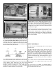
Set the Control Throws
❍ Use a Great Planes AccuThrow (or a ruler) to
accurately measure and set the control throw of each
control surface as indicated in the chart that follows. If your
radio does not have dual rates, we recommend setting the
throws at the low rate setting.
NOTE: The throws are measured at the widest part of the
elevator, rudder and ailerons.
These are the recommended control surface throws:
High Rate Low Rate
ELEVATOR: 1/2” [13mm] up 3/8” [9.5mm] up
1/2” [13mm] down 3/8” [9.5mm] down
RUDDER: 1” [25mm] left 1” [25mm] left
1” [25mm] right 1” [25mm] right
AILERONS: 5/8” [16mm] up 1/2” [13mm] up
5/8” [16mm] down 1/2” [13mm] down
IMPORTANT: The Tower Trainer 40 MKII ARF has been
extensively flown and tested to arrive at the throws at
which it flies best. Flying your model at these throws will
provide you with the greatest chance for successful first
flights. If, after you have become accustomed to the way
the Tower Trainer 40 MKII ARF flies, you would like to
change the throws to suit your taste, that is fine. However,
too much control throw could make the model difficult to
control, so remember, “more is not always better.”
24