
Instruction manual
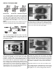
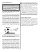

❍ 6. Carefully align the nose wheel as straight as possible.
Align the steering pushrod with the second hole (out from
the center) in the rudder servo arm and place a mark on the
steering pushrod as shown in the above photograph. As
you did with the previous pushrods, make a 90-degree
bend at the mark, install the servo arm and the Faslink, and
cut off the excess steering push rod. Put the rudder/nose
gear steering arm on the servo with the screw.
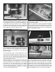
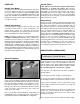
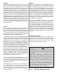
❍ 7. Install the throttle servo into the servo tray as shown
above using the same method used to mount the previous
two servos with the servo mounting screws. Center the
throttle servo arm on the throttle servo as shown in the
above photograph.
Cut the guide tube using a sharp hobby knife at the
location in the photograph. Remove the throttle servo arm
and install the screw lock pushrod connector in the last
hole on the servo arm. Slip the throttle pushrod into the
screw lock pushrod connector and reinstall the servo arm
onto the servo with the screw.
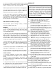
Before tightening the screw lock pushrod connector look
inside the carburetor on the engine and move the throttle
pushrod until the barrel of the carburetor is ½ open. With
the throttle servo arm still centered on the servo, tighten
the screw on top of the screw lock pushrod connector.
Using the above photograph as a reference, cut off the
excess throttle pushrod but leave a minimum of ½” (13mm)
of excess rod for adjustments later.
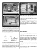
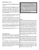
❍ 8. Install the battery/receiver mounting plate into the
fuselage using four 2.6mm x 8mm wood screws as shown
in the above photograph.
Note: You may place the supplied hook and loop material
into the battery/receiver mounting plate prior to mounting
the plate into the fuselage. It is a bit more difficult if you
wait to do this when you mount the receiver and battery.
Refer to step #10 for location.
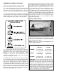
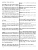
❍ 9. Locate the cutout for the on/off switch on the left
side of the fuselage, away from your engine exhaust and
cut the covering from this cutout. Remove the cover plate
from the radio system on/off switch and use it as a pattern
to drill the two holes on either side of the cutout. This will
allow you to mount the on/off switch by placing the two
screws back into the cover plate and placing them through
the fuselage side. Hold the on/off switch in place and
reinsert and tighten the two screws in the on/off switch.
22