
Instruction manual
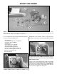
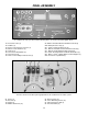

HOOK UP THE CONTROLS
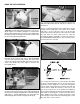
❍ 1. There is a 5mm hole in the firewall for the pushrod
guide tube that will align with the throttle arm on most two-
stroke engines. Use medium sandpaper to roughen both
plastic pushrod guide tubes. Insert one pushrod guide tube
through the hole in the firewall for the throttle, and the other
for the steering pushrod guide tube.
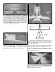
❍ 2. Thread a nylon clevis 25 full turns onto the 500mm
threaded throttle pushrod wire. Slip a silicone retainer
over the clevis. Insert the pushrod with the clevis all the
way into the throttle pushrod guide tube and connect the
clevis to the throttle arm on the engine as shown in the
photograph above.
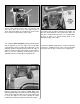
❍ 3. Run the un-threaded 500mm steering pushrod through
the Screw Lock Pushrod Connector and continue pushing it all
the way into the steering rod guide tube. Position the pushrod
guide tubes to extend approximately 1/8” [3mm] past the
firewall and glue them into place using 6-minute epoxy.
❍ 4. Screw two nylon clevises 25 full turns onto the two
680mm threaded wire pushrods. Slip silicone retainers over
the clevises.
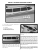
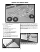
Slit the covering material where the guide tubes exit the
fuselage with a hobby knife. The location of the rudder
tube exit is on top of the fuse next to the fin and the
elevator tube exit is located on the same side of fuse under
the stab. After you have made your cuts, slide the
pushrods through the guide tubes. Connect the clevises to
the control horns placing them in the second hole from
the end of the horn as shown.
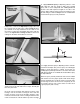
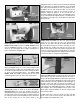
❍ 5. Position the control horns on the elevator and rudder
as shown in the photograph. The row of holes in the horns
should be over the hinge line. If necessary small bends
may be made in the pushrods to position them with the
control surfaces. Mark the locations of the holes in the
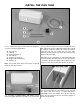
base of the control horns on the elevator and rudder. At
these locations drill 5/64” [2mm] holes through the elevator
and rudder for mounting the control horns with 2mm x
14mm phillips head screws, and then mount the control
horns using the screws and the nylon backing plates on the
other side of the control surfaces.
20