
Instruction manual
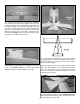
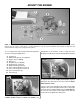
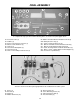

#1 Servos (3)
#2 Receiver (1)
#3 Switch (1)
#4 Rubber Grommets (12)
#5 Brass Eyelets (12)
#6 Servo Mounting Screws (12)
#7 Aileron Extension Wire (1)
#8 Receiver Battery (1)
19
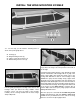
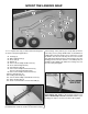
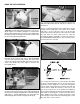
FINAL ASSEMBLY
#1 Protective Foam (2)
#2 Faslinks (2)
#3 Screw Lock Pushrod Connector (1)
#4 Silicone Clevis Retainers (3)
#5 Clevises (3)
#6 Control Horn Backplates (2)
#7 Control Horns (2)
#8 2mm x 14mm Phillips Head Screws (4)
#9 680mm Threaded Elevator-Rudder Pushrods (2)
#10 Battery/Receiver Tray (1)
#11 2.6mm x 8mm Wood Screws (4)
#12 105mm Threaded One End Throttle Pushrod (1)
#13 105mm Un-threaded Steering Pushrod (1)
#14 Plastic Steering/Throttle Pushrod Guide Tubes (2)
#15 10mm x 13mm x 80mm Balsa Pushrod Support (1)
#16 Hook and Loop Material (2)
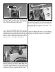
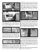
To complete this step you will need the following items, as shown in the photograph above.
The items shown in the above photograph will also be needed from the radio system.