
Instruction manual
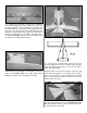
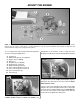
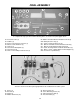

❍ 4. Install the nose gear by attaching the nose gear
bearing bracket to the firewall with two 4mm x 12mm
Phillips head screws and the two 4mm washers which
must go behind the bracket so they act as spacers as
shown in the photograph above. Apply Threadlocker to
these screws before installing them.
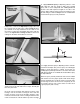
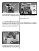
❍ 5. The steering arm should be cut off as shown in the
above photograph. Place one of the wheel collars into the
steering arm base, making sure the threaded hole for the
set screw is aligned with the hole in the steering arm base
as shown in the photograph above. The 3mm x 8mm
Phillips head set screw is then placed into the wheel
collar through the hole in the base of the steering arm.
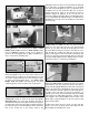
❍ 6. Place the screw lock pushrod connector onto the
steering arm exactly as shown in the above photograph.
Important Note: The screw lock pushrod connector is
assembled in the bag. In order to place it onto the steering arm
you will need to remove the wheel-type nut and the washer on
the end of the unit. Insert the threaded stem of the unit into the
hole on the steering arm in the manner shown in the
photograph. Place the washer on the threaded stem followed
by the wheel-type nut. Apply Threadlocker to the threaded
stem and then gently tighten the nut. It is important not to
overtighten this nut; this would not allow the screw lock
pushrod connector to rotate on the steering arm while in
operation. Adjust the tightness of the nut and test the
connector’s ability to rotate but still be somewhat tight. When
you are satisfied with this adjustment place a small amount of
Threadlocker on the top of the nut and allow it to wick down
into the threads.
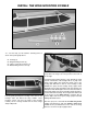
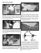
❍ 7. Place another wheel collar with a 3mm x 5mm
Phillips head set screw onto the nose gear wire then
insert the nose gear wire into the nose gear bearing
bracket. As you slide it through the bearing bracket, hold
the assembled steering arm in place and slide the nose
gear through the steering arm and into the hole in the
bottom of the engine mount. Note that the existing flat spot
on the nose gear wire is facing forward. When you have the
nose gear installed tighten the two Phillips head set screws
in the wheel collars to complete the installation.
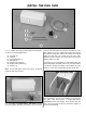
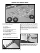
❍ 8. Place a wheel collar and a wheel on the nose gear and
landing gear axles. Add the second wheel collar on the outside
of the wheel to each axle. Center the wheel on the axles as
shown in the photograph. Mark the location of the outer wheel
collar on the axles with a felt tipped pen. Remove the wheel
collars and wheels. Then file or grind a 1/4” [6mm] flat spot on
the axles of the main and nose gear at the locations you
marked. This is done to prevent the wheel collar from turning
or becoming loose during flight. Secure the 3 wheels on the
axles using the 3mm x 5mm Phillips head set screws in the
wheel collars, using Threadlocker on the set screws to hold
them securely in place.
Double check all the wheels to make sure they still spin
freely. If not, move the inner wheel collar away from the
wheel slightly and retighten the screw.
18