
Instruction manual
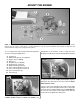
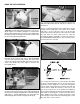

❍ 4. With the engine in place, install the remaining two
4mm x 25mm machine screws, 4mm lock washers, and
4mm nuts in place at the front of the engine mount as
shown in the photograph. Do not tighten the screws at this
time to allow for the positioning of the engine.
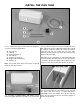
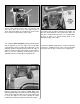
❍ 5. Install the spinner backplate, propeller, propeller washer
and the propeller nut onto the engine. Turn the propeller
counterclockwise until it is against the smallest pins on the
backplate. Keep the propeller horizontal when the engine is
against its compression [the point at which you feel resistance
when you turn the crankshaft counterclockwise]. Use an
adjustable wrench to securely tighten the propeller nut.
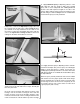
❍ 6. Measure the distance from the spinner backplate to the
firewall. It should be 3-3/4” [95mm] on both sides of the
spinner backplate. Adjust the engine if needed and tighten the
screws evenly, using Threadlocker on the screws and the nuts
to secure the engine to the mount. Following the engine
manufacturer’s instructions, install the muffler to the engine.
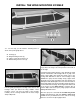
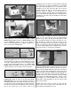
❍ 7. Attach the silicone fuel lines to the engine. The line
you marked “Vent” should be attached to the muffler. The
other line will be attached to the needle valve. Make sure
there are no sharp bends in the lines. If so, carefully adjust
the lines to allow for a smooth flowing bend to the
appropriate fitting of the engine.
8. Attach the spinner cone with the screws provided. Be
careful not to overtighten these screws. They are threaded
into plastic that can strip out if they are over tightened.
16